Electromagnetic simulations as part of your design process, that’s EMAG-nificent
Electromagnetics (EMAG) and electrical engineers are at home with streamlined EMAG Computer Aided Engineering (CAE) packages, like Simcenter SPEED, Simcenter Motorsolve, and Simcenter MAGNET. Our functional Computer-Aided Design (CAD) colleagues generate a defeatured geometry of only EMAG active parts for us. If we face CAD issues such as extracting the geometry from an assembly or meshing errors, we automatically push the design back to the CAD designers, and the clock starts ticking.
Can we continue like this?
With the race to electrification, there is a need for more cooperation across different teams. Product designers give us “the look and the feel” of the product – the skin. CAD designers distribute real estate. CAE engineers then work within constraints to add the physics needed to optimize the product.
Spending some time on communication and alignment between teams is seen as an inherent part of the process “it’s just how these things work in big companies,” is a common aggrievement. Sub-optimal processes may have been fine when electromagnetic components were an accessory to your product. However, nowadays, an electric drive is at the core of many products, and wasting time in iterations with other departments can double your development cycles and skyrocket R&D costs. Furthermore, the high competition and the lack of engineering resources make it unsustainable to keep wasting time on meaningless iterations.
What about upstream CAD changes that affect the EMAG bodies?
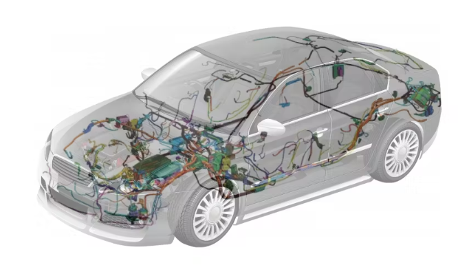
It is not unusual for an EMAG engineer working on an e-powertrain to receive a detailed CAD neutral file. Often these files, although consisting of a housing and transmission assembly, are non-associative (we will discuss what non-associative means later). The files will be missing the rotor, stator core, or both and are more visual than functional for CAE. This sets off a back and forth between the EMAG and CAD teams, who now need to clean up and simplify the geometry and verify the materials. Only after this clean-up process can an electromagnetics engineer start their real work of searching for a concept and validating the proposed design.
Due to the current soaring interest rates and higher costs, Project Managers in the EV (Electric Vehicles) space are under elevated pressure since 2018, to hit vehicle delivery timelines at elevated costs if left unchecked. As a result, you may hear yours asking your team to shed weight and volume from components. As an EMAG engineer, you will find yourself crafting a way to hustle the CAD designers of their time. Rest assured; you aren’t the only one. CAD designers must reflect the new CAD updates and help CAE teams update their geometries. As you can imagine, the emails, calls, and meetings to make this happen are extensive, and the impact on the timeline to market is enormous.
How can we save time?
A system that allows the electromagnetics engineer to automatically update their models to the latest CAD design, with minimal input from the designer, will increase productivity. You can see an example of a possible process in this short video. The video shows how to update an extracted 2D e-motor geometry from a vehicle assembly due to upstream changes to the stator outer diameter.
The video starts by focusing on the e-powertrain, and gradually isolates the e-motor from the rest of the assembly. Next, we not only grab the electromagnetic active bodies but also associate them with the assembly. Then, we add all we need for our simulation: the air and re-mesh regions, the rotor 2D geometries, and the finite elements mesh for completeness. Finally, we trigger an upstream change to the stator outer diameter, which you can see in the updates in the mesh. The CAD connection of the Simcenter environment empowers you to concentrate on your job – electromagnetics analysis.
Now let’s turn our attention to the global push for lightweighting and integrating e-powertrains. There is a need to control noise levels and get rid of the heat in ever smaller electric –motor sizes. These need more complex liquid cooling, and designs that ensure the magnets do not fly off, all of which will change the electromagnetic’s structure.
How do you update the electromagnetics model with multi-physics-driven geometric changes?
In a traditional workflow, the non-associated model updates made by other groups would require the EMAG engineer to repeat the workflow hustle with the design team and all its associated emails and calls. You will feel damned if you have no associativity! On top of that, the problem only gets worse by increasing the number of physics domains under consideration.
E-powertrains undergo an entire range of multi-physics simulation iterations before the engineers settle on a design. These horizontal changes are mutually driven by electromagnetics, thermal, structural, and noise and vibrations (NVH) analysis. With engineers from each department working simultaneously with a non-associative tool, the possibility of an engineer working on an out-of-date model instead of the current best design is remarkably high.
How do you keep track of the updated CAE geometry?
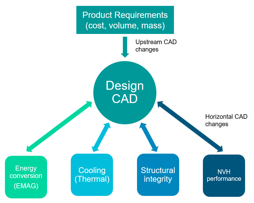
Luckily, there is a reference – though subtle in a siloed environment. The design CAD is the only common link between physics, and the product requirements, such as cost, which is pegged to the volume and mass. As illustrated in Figure 2, if the design CAD is seamlessly updating, it means all the CAD and all CAE engineers are accessing the same geometry at any one time. Obviously, the updating and access are controlled in a managed environment. This means you won’t have stale results in your project meetings. For electromagnetics, geometry will reflect the recently approved upstream and horizontal changes.
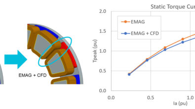
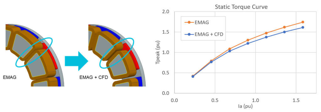
For example, in Figure 3, we see the evolution of the EMAG stator parts from an efficient design based only on electromagnetic performance to one that accommodates the cooling channels on the coils. We see a reduction in the torque because the volume is now constrained. That is because the first design contains more steel and can therefore carry more magnetic flux.
As we can see in the video, we can associate the electromagnetic’s active parts with the CAD design. After a parametric study to choose the final channel width, this geometric change was introduced into CAD design. And because the geometry used for the electromagnetics simulation is associative, it was just a matter of re-running the solve with the changes
What does this really mean?
- In a multi-physics design process like the one required for an e-machine, having a streamlined workflow can save hundreds of engineering hours. You only spend the initial setup effort once! The rest is just on iterating the design driven by both product requirements and physics changes.
- The associated workflow helps us overcome our siloed approach and single physics bias in development. An efficient electromagnetic device may not be structurally sound or even possible to manufacture. By capturing what is possible via geometric constraints and physics interactions, we get to a more realistic design. At the same time, it helps us manage our own internal physics bias and work together towards a good balance of performance. Whatever we think is suitable for our physics may not necessarily be good for the overall product performance. An integrated design process allows us to do these iterations and converge much faster!
In summary, the associated process discussed in this blog reduces time wasted so products can be developed quicker. This process helps engineers and designers settle on a concept quicker by ensuring everyone is working on the most up-to-date model. While ensuring that disadvantages such as bias towards particular physics models or siloed teams do not occur. Build your next e-motor quicker, better, and in terms of engineering hours, cheaper.
Related resources
Webinar
Achieve EMC compliance for electrified vehicles with electromagnetic simulation

White paper
Aircraft electromagnetic compatibility
White paper
Address EMC/EMI and thermal issues in electric vehicles
Blog
Viewing the invisible: simulating electromagnetic performance


