What’s new in Simcenter 3D Rotor Dynamics 2606 – Postprocess modes at critical speeds and efficiency updates

Why do we need rotor dynamics analysis?
Modern turbomachinery, from jet engines to industrial compressors, runs at high speeds and under heavy loads, where even small prediction errors can cause vibration, instability, or failure. Rotor dynamics analysis helps engineers assess how shafts and rotating assemblies behave across the operating range, identify critical speeds, and pinpoint modes that could trigger resonance and reduce performance, safety, or service life.
Simcenter 3D Rotor Dynamics, including Simcenter Nastran SOL 414, helps engineers analyze vibration in rotating machinery, predict resonance at critical speeds, evaluate bearing loads, and assess system survivability under realistic operating conditions
What’s new in Simcenter 3D Rotor Dynamics 2606
In the Simcenter 3D 2606 release, users can make the simulation process more efficient by accessing essential results in the analysis, with fast processing. In this blog, we present three highlights in the 2606 release:
- Postprocessing of modes at critical speeds
- Computation of energy distribution in the full assembly, (even if superelements are used)
- A faster results format: the Simcenter data file (.scd5) that uses HDF5 architecture
Critical speeds of the rotating assembly
The computation of an assembly’s critical speeds is essential to the design of a turbomachine. Furthermore, the operating speed range must be far enough from the critical speeds of the system to avoid the resonance phenomenon occurring and inducing high levels of vibrations. Later, we will discuss what ‘far enough’ means and how we can visualize the permitted operating speed range where the turbomachine can operate safely.
With the 2606 release, modes corresponding to critical speeds of each rotor can now be output as results of a Nastran SOL414 complex modal analysis, together with the Campbell and stability diagram.
In this picture, the complex modal analysis computes the Campbell diagram with modes corresponding to the critical speeds for rotor 1 (yellow circles) and rotor 2 (purple circles) when the speed ratio between the two rotors equals 2.0.

This capability is more than a direct critical speeds analysis, as a direct critical speeds analysis is an undamped analysis, with constant bearing properties. With this new capability, you can output modes at critical speeds for each rotor. This removes the limitations of direct critical speeds analysis because damping can be defined in the simulation to compute the stability of the rotating system (viscous damping, modal damping, or hysteretic damping in the connections), and bearing coefficients can be functions of the rotation speeds, which is closer to the realistic conditions.
Modes at critical speeds are output for critical speeds at order 1, for a simulation of one or multiple rotors, computed in an inertial frame. Rotors can be modeled by all types of modeling approaches: 1D beam, 2D Fourier multi-harmonic, 3D solid axisymmetric models, 3D cyclic symmetry including the Coleman transformation, and superelements.
Results that can be output at critical speeds are mode shapes, stresses, energies, and energies distribution (strain, kinetic and dissipation) in groups of elements. By outputting modes at critical speeds only, instead of at all rotation speeds at every step of the computation, you can decrease the size of the results file by a factor 10, potentially saving a huge amount of resources when results files are stored in a data management system.
Energy distribution in the different components of the rotating assembly
When analyzing an assembly’s energy distribution at a given rotational speed, such as the critical speed, you can see for each mode which parts are most affected if the corresponding mode is resonant. The energy distribution for a group of elements is presented as a percentage of the total energy, for the strain, kinetic, and new in 2606, the dissipation energy associated with damping.
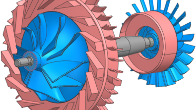
In the demonstration below with the two connected rotors, the low-pressure rotor and high-pressure rotor, we can study the compressor and turbine parts. Then, four different groups can be studied separately for the energy distribution: the low-pressure rotor compressor and turbine, and the high-pressure rotor compressor and turbine.


The first critical speed at order 1 (40 Hz) shows that most of the energy is found in the compressor part of the low-pressure rotor, indicating that this part has a higher risk of deformation if this mode is activated. This type of information is very important if we want to identify which modes are most dangerous and in which part of the structure they occur.
What happens to the energy distribution when the structure is condensed into superelements
Superelements are used a lot in rotor dynamics as this area of dynamics is used in the context of small deformations. Even if the rotor dynamics simulations can manage geometric nonlinearities, the structure is computed in the linear domain. The use of Craig-Bampton superelements is relevant and very efficient in this context to drastically reduce the computation time of the simulation.
From past releases, we already know that Simcenter Nastran SOL 414 superelements for rotors enables you to output XY Plots at internal nodes of the superelements. This removes the requirement to define retained nodes on the structure that will only be used to monitor results. For energy distribution, if superelements were used in an assembly, it was not possible to access elements inside the superelements for the calculation of the energy distribution. Indeed, the energy distribution was output by considering the superelement as a whole entity.
Starting from Simcenter 3D 2606, if engineers configure groups of elements for energy distribution at the creation step of a Simcenter Nastran SOL 414 superelement, for a rotor or a stator, those groups can be used later for outputting the strain, kinetic and dissipation energy tabulations when the simulation uses the structure condensed in superelements. This capability makes the process more efficient for engineers who leverage the advantages of superelements. Indeed, the recovery of results on the original structure is not needed in this process. The energy tables are generated directly by the simulation process during an eigenvalue analysis, complex modal analysis, or harmonic response.
The demonstration hereafter differs from the previous demonstration in that it uses superelements. When the structure is condensed in superelements, the groups of elements are not available, but the user can ask the simulation to use the groups configured at the creation for outputting the energy distribution.
Advantages of simcenter data files for the postprocessing
Simcenter 3D Rotor Dynamics outputs the results in an efficient format based on an HDF5 architecture, the .scd5 (Simcenter data file) file. It can be easily and quickly uploaded to Simcenter 3D.
This result file presents different advantages: there is one single .scd5 file for a simulation, which contains all the results: spatial results for the different subcases, on the selected nodes and elements, or on the whole structure, and the different XY Plots.
For engineers working in gas turbine applications and working with API 616 requirements, they can ask for additional XY Plots that enable them to visualize the operating speed range that is ‘far enough’ from critical speeds. Where ‘far enough’ is computed by analytical formulae for the separation margins and amplification factors, provided by the API 616 requirements.

Specific functions in the postprocessing of rotor dynamics results enables you to extract results such as the width of the operating speed range, the amplification factors of a selected vibration peak, and the frequency at which the peak occurs. These are then available for later use in an optimization or design of experiments process.
Conclusion
How does Simcenter Nastran 2606 enable you to boost the efficiency of rotor dynamics simulations?
Three areas will significantly help you in this release: the postprocessing, the modeling of rotors and casing, and computations using High-Performance Computing.
Efficiency in postprocessing
- The efficiency of the postprocessing when using the simcenter data file for the analysis of the results which provides fast and complete postprocessing
- The efficiency of the generation of results that the users are most interested in, such as the modes of the whole structure at critical speeds only, or the energy subdivision by groups of elements, even if the structure is represented by one or multiple superelements
Efficiency in the modeling of rotors and casing
In previous blogs, we also showed the efficiency in the representation of the original structure by reduced, but accurate modeling approaches like 2D Fourier multi-harmonic model, cyclic symmetry, or superelements, that takes advantage of axisymmetry, periodicity, or linear behavior of the system.
Efficiency of the computations using High-Performance Computing
In this previous blog, we run a complex modal analysis on AMD Central Processing Units (CPUs), and analyzed the performance gain offered by the Distributed Memory Parallel (DMP) processing.
We analyzed two distinct parallelization methods: distributing independent job steps across different processors or solving each individual step using multiple processors.
Best practices for the computation of rotor dynamics simulations in parallel were deduced and presented.
Related blogs on rotor dynamics
Did you enjoy reading this blog and want to know more? You may also like the following blog posts:
Simcenter 3D 2512: Active magnetic bearings in turbomachines
Rotating systems – tune your intuition
Efficient rotor dynamics for multi-stage turbo machinery
Containing aircraft engine failure
Combine solution speed and accuracy for axisymmetric rotor dynamics
Bearing modeling makes or breaks rotor dynamics simulation
Multi stage cyclic symmetry in rotor dynamics
Advances in resonance and cyclic symmetry of bladed rotor assemblies
Identify the peaks of harmonic response during operation of nonlinear rotor dynamics
Smooth vibrations in rotating systems – How to monitor clearance consumption
Turbomachine assemblies and the challenges of designing them