Advances in resonance and cyclic symmetry of bladed rotor assemblies – Simcenter 3D 2306
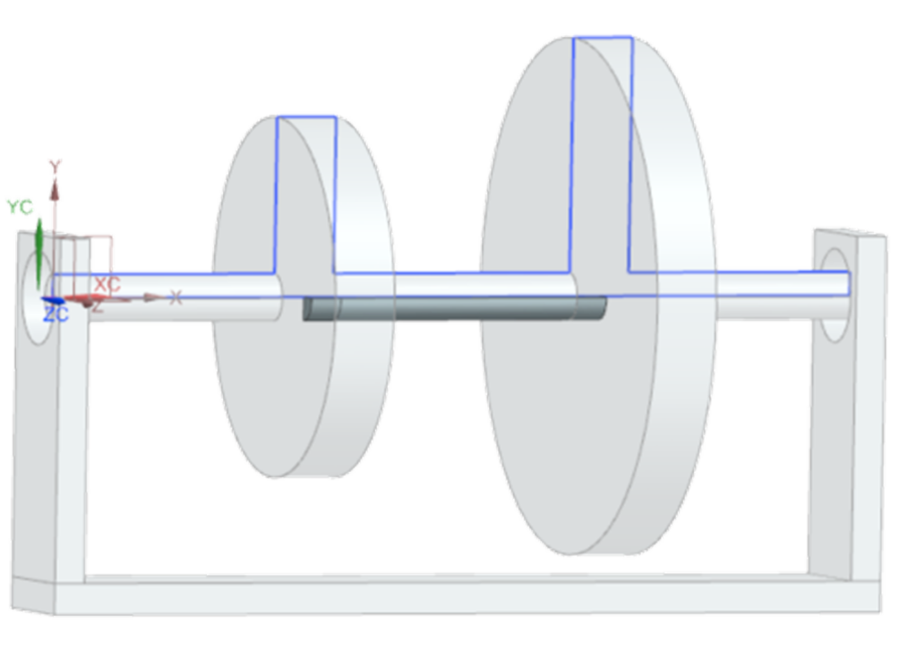
Rotating systems are often made of bladed rotors connected to a casing through bearings, and often exhibit cyclic symmetry.
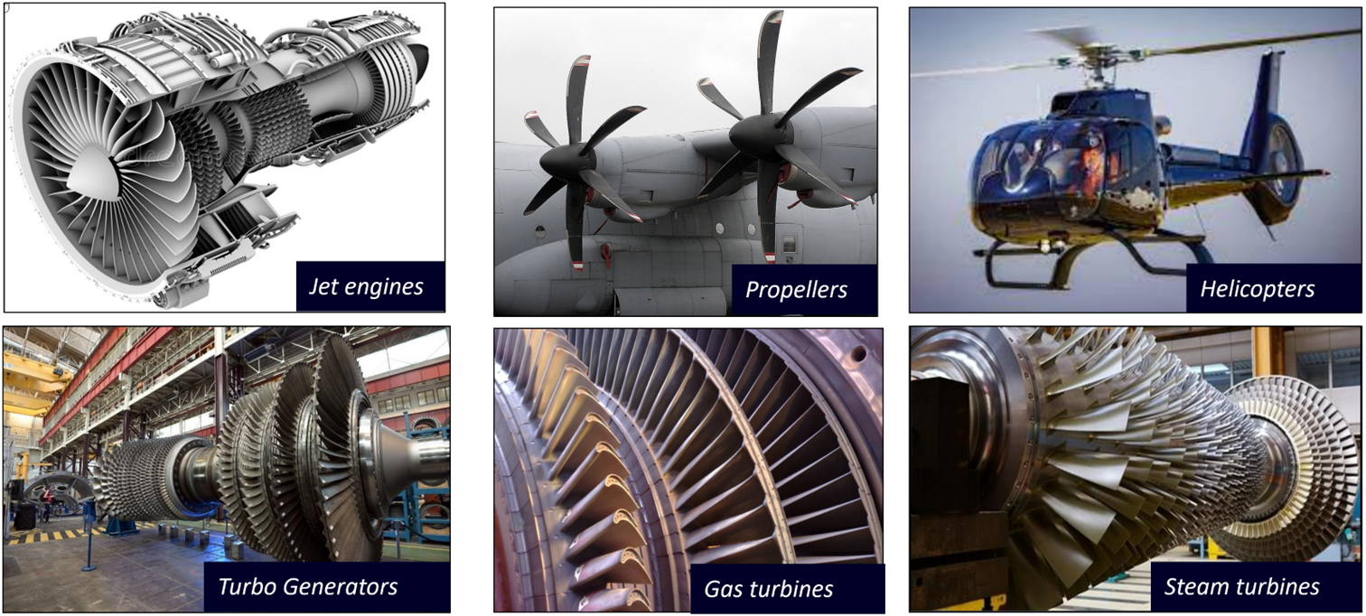
Such rotating systems are widespread in the energy, aerospace and defence, marine, or more globally rotating machinery industries. Let’s consider a subgroup that includes jet engines, propellers, helicopters, turbo generators, gas or steam turbines, and pumps. To fully understand the loading on such machines for analysis such as lifing, one often observes the whole assembly of the different components because coupling between the different parts, may affect the vibrations, resonance, and the lifetime of the full system.
Bladed rotors are particular…
An essential concept in rotor dynamics is the concept of axisymmetry, the symmetry around the rotation axis, because the equations used to calculate the vibrations of rotating systems are not the same for axisymmetric and non-axisymmetric machines.
Some bladed rotors are considered axisymmetric, for instance, when there are many blades around the rotor axis. Newer systems have thinner and longer twisted blades that can handle more deformation to reduce weight and enhance engine performance. These new designs are shifting away from the hypothesis of an axisymmetric rotor.
Moreover, some applications like propellers have few blades and therefore definitely cannot be considered axisymmetric.
Axisymmetric vs cyclic symmetry:
A model is axisymmetric if you can take a 2D portion in the meridian plane and build a revolution solid i.e. a continuous drum. While a structure with cyclic symmetry has periodicity, with a sector that can be reproduced N times around the axis i.e. blades of a turbine. learn more about the benefits when simulating with these two methods here
Reducing model size with cyclic symmetry
Fortunately, engineers are not limited to creating full 3D models for bladed rotors, as they are often not axisymmetric. The blades’ periodicity establishes a sense of symmetry, which is commonly found in cyclic symmetrical structures. A sector, or a group of sectors, can be isolated, modeled in 3D, and studied. With the capability of recombining results afterwards in full 3D, studying a single sector of cyclic symmetry is an interesting alternative to 3D models.
In an earlier blog, we explained how to take advantage of a cyclic symmetrical structure to reduce the model size, even if the application contains different stages that have a different number of sectors.
Simulation with a model that has cyclic symmetry
When the blade is long, thin, and twisted [external blog: example of a steam turbine, where the last stage has long, thin, and twisted blades], the application is no longer an axisymmetrical model, as explained earlier. Now, to satisfy the rotor dynamics theory, the model must be solved in a rotating reference frame, rotating with the rotor. Although the simulation is possible in a rotating reference frame, it provides some limitations: only one rotor can be used in the assembly; if a casing is modeled, it must be axisymmetric, and bearings must be isotropic.
If those conditions of isotropy are not satisfied, the rotor is solved in the rotating reference frame and the casing and the bearings are solved in the fixed reference frame. Simcenter 3D and Simcenter Nastran offer the necessary coupled simulations in the transient analysis, as explained in our previous blog.
With the latest updates to Simcenter 3D 2306 and its integration with Simcenter Nastran, it is now possible to remove these restrictions. The Simcenter 3D update considers a cyclically symmetric sector connected to bearings that can be either isotropic or anisotropic (stiffness and damping properties unequal in all directions or described by a function of the rotation speed), and computes the complex modes, complex eigenfrequencies, a Campbell diagram, and damping diagram for the stability of the assembly in the fixed reference frame. The solver first computes results in a rotating reference frame for the rotor part and then converts those results to the fixed reference frame using the Coleman transformation we describe later.
Additionally, vibrations can now be studied with cyclic symmetrical structure through a modal harmonic response via passing the computation of an equilibrium of a prestressed structure due to centrifugal loads allowing you to fully understand all the loads exerted on the whole system for the life of the system.
Coleman transformation for cyclic symmetrical structure
In the fixed reference frame, unsymmetric rotors with anisotropic bearings would require special methods, and lead to systems with time-dependent, and periodic matrices. To proceed with time invariant matrices, rotor models must be isotropic in the inertial (fixed) frame when coupled to non-isotropic supports.
When we have a full non-axisymmetric assembly (e.g. a non-axisymmetric rotors, coupled to non-axisymmetric stator, connected by anisotropic bearings), there is a method called the Coleman Transformation, that can produce time invariant matrices in the fixed frame for cyclic symmetrical rotors (e.g. Kirchgassner 2016), for the calculation of the critical speeds at which resonance occurs, Campbell diagram and stability analysis. This method is equivalent to the Floquet method when the structure is strictly cyclic symmetrical (Skjoldan 2009).
To clarify, applying a Coleman transformation allows for the conversion of results calculated in a rotating reference frame to a fixed reference frame. Response in the fixed frame is normally periodic but the Coleman method allows to obtain fundamental frequencies and time-invariant matrices.
Applying the Coleman method in Simcenter 3D
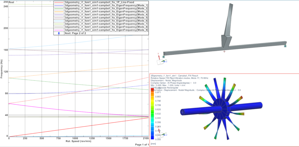
The workflow has been straightforward in Simcenter 3D. For a cyclic symmetrical structure mounted on its bearings, a complex modal analysis SOL 414,110 can be defined in Rotating reference frame. Activating the Coleman transformation leads to Campbell diagram, damping diagram, critical speeds, whirling, in the fixed reference frame, and fully recombined mode shapes in 3D.
Conclusion
As the weight of rotating machines decreases and performance improves, it is essential to account for the entire assembly when calculating potential resonance. Resonance happens at critical speeds where high levels of vibrations can be reached, causing potential damage on the structure. This blog post highlights how Simcenter 3D employs cyclic symmetry to reduce model size and calculate critical speeds and stability by exploiting the structure’s periodicity. The post specifically focuses on the bladed rotor assembly mounted on its bearing and presents results in the fixed reference frame.
Simcenter Mechanical release
This blog was released as one of a series celebrating the release of the Simcenter Mechanical solutions products. Other blogs that were released in this Simcenter Mechanical series include:
Strength and fatigue analysis wizard guides you to the results – Simcenter 3D 2306