Identify the peaks of harmonic response during operation of nonlinear rotor dynamics

Rotor dynamics is the discipline in the structural dynamics’ world that studies vibrations in rotating machineries. Although measurements are recorded in the time domain, engineers are interested to see what’s happening during a revolution of the system, at a specific rotation speed, and then at a specific frequency. Studying the vibrations of the system for different frequencies leads to calculations in the frequency domain, well known as ‘Harmonic Response’.
With this type of simulation, engineers study how defects in the rotating system like an unbalance or a misalignment induce undesirable vibrations during operations, or more generally, they study the effect of frequency-dependent load applied to the rotor or to the casing, e.g. the vibrations due to an earthquake.
Concepts of synchronous/asynchronous harmonic response
In Harmonic response, the simulation is computed in a range of frequencies. In some cases, the frequency corresponds to the rotation speed of the rotor, we are then referring to synchronous analysis. In other cases, the excitation frequency is different from the rotation speed of the rotor, referred to as asynchronous analysis. As a result of this analysis, we monitor quantities like displacements, forces, stresses, as function of frequency, what we also call Frequency Response Functions FRFs. Each point of the Frequency response function corresponds to a specific frequency response. The results of harmonic response are complex numbers: they make it possible to represent the system behavior over a full cycle as depicted on the above orbit plot.
Types of result
In the animation below, the FRFs (top right) represent the evolution of the magnitude of the displacement of the smaller disk’s center, in a frequency range from 1 to 65 Hz, for the unbalanced rotor. Resonance is found for 2 frequencies, around 14Hz and 47Hz. At 47 Hz, the animation of the deformed shape is presented (left), and the movement of the center of the smaller disk, at a frequency of 47Hz, is represented (bottom right).
Extended video on the fundamentals
Identify the peaks of the resonance and stability during operation
As shown in the animation, in Frequency Response Functions resonance frequencies can be identified where vibrations form peaks at their maximum amplitude. Depending on the loads, resonance occurs when the rotation speed matches the eigenfrequency of the corresponding modes. Flexible rotating systems are highly influenced by gyroscopic effects as we discussed in our previous blog. Therefore, the natural frequencies you calculate on the structure at rest are no longer the same when the system rotates. Indeed, the gyroscopic effects will duplicate some eigenmodes into forward and backward whirling modes, and whose eigenfrequencies vary (increase or decrease) with the rotation speed. These changes in eigenfrequencies show that the stiffening and softening of the system impacts the behavior of the system at high rotation speeds.
Rotor dynamics is the unique discipline that studies this phenomenon so to predict vibrations in flexible rotating structures in a high range of situations.
Resonance frequencies of rotating systems can be calculated in a preliminary analysis, which is known as Complex Modal Analysis. It has the advantage of calculating all critical speeds, independently of the type of loads that will affect the structure afterwards.
Damping usually decreases amplitude near resonance frequencies typically by decreasing the amplitude of the displacement. However for unstable systems at particular rotation speed ranges, damping can cause vibrations with higher amplitude that can damage the system (learn more).
Knowing the critical rotational speeds at which resonance occurs and assessing the stability of the rotating system is a top priority for engineers in rotor dynamics simulations.
Demonstration
Bearings: What influence?
The dynamics of the system is highly influenced by the way in which the different components are assembled. In all types of rotating systems, bearings can play the role of connecting the different parts (see bearings blog). Their stiffness and damping characteristics are essential in order to reproduce the dynamics behavior of the system. However, those characteristics are never constant during operations. The latter depend on the rotation speed, temperature, and the position of the rotor shaft inside the stator.
When an engineer wants to reproduce the dynamic behavior of a system, they typically follow a three-step process. First, they perform a static calculation to determine the load on the bearing. Next, they use the standard code of bearing to derive the stiffness and damping evolution as a function of the rotational speed for the computed loads. Finally, they import the derived functions into Simcenter 3D Rotor Dynamics and use them to perform various types of rotor dynamics analysis, such as calculating critical speeds and stability, or determining the forced response to defects like imbalance or misalignments, or to frequency or time-dependent loads.
The difficulty of nonlinear bearings
What happens when an engineer has their own bearing model, or if they are using the nonlinear models in Simcenter 3D Rotor Dynamics?
Real bearings have a nonlinear behavior. In a situation that requires nonlinear analysis, only transient and harmonic responses can be used. Other analyses like maneuver loads or complex modal analysis are linear analyses, and are only suitable to linear models. Therefore, including bearings their geometric nonlinearities makes the whole model nonlinear. This prevents the calculation of the critical speeds and stability before any forced response.
Calculate the critical speeds and stability for a nonlinear system
In Simcenter 3D, calculating a complex modal analysis (Campbell diagram, critical speeds, and stability analysis), normally restricted to linear systems, can also be computed from a nonlinear harmonic response.
The scenario is the following: at an occurrence defined by the user, for instance every 5 frequency steps, a tangent system is computed, and complex modes and eigenfrequencies can be calculated. After the simulation, the modes’ eigenfrequencies are collected and the modes’ evolutions are tracked in a Campbell diagram.
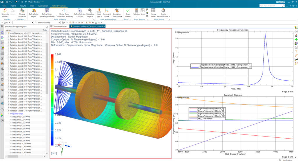
In this figure there are three images: on the left we see the deformed shape. The top right image shows the vibration level as a function of frequency. In the bottom right image, we can observe the peak calculated at the critical speed by the Campbell diagram for the corresponding forward mode. The critical speeds stand at the intersection between the mode 9 in green and the 1P line
At the end of the harmonic response analysis, the engineer gets the vibrations as function of frequency (Frequency Response Functions), as well as deformed shapes of the structure for selected frequencies, orbit plots, and the Campbell diagram from which critical speeds can be assessed as well as the mode shapes for different rotation speeds. While, the stability can be evaluated from the damping diagram.
In Summary
With harmonic response, the engineer has the possibility to study the behavior of its rotating system in steady state conditions for different frequencies and rotation speeds. With such analysis, defects such as unbalance or misalignment can be studied in a frequency range. In this blog, we have shown the possibility of computing a Campbell diagram, critical speeds at which resonance occurs and the stability of a system that contains geometric nonlinearities coming from their bearings.
Simcenter 3D includes dedicated tools to complete all the steps in the process. Those include specific functionalities rotor dynamics engineers would need to apply realistic boundary conditions, to effectively prepare geometries and perform meshing, to do more efficient calculations and to get more insightful post-processing.