Rotor dynamics: when accuracy is a matter of life and death
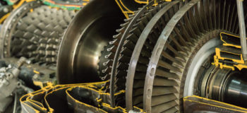
Rotating systems are at the heart of almost any mechanical structure. They are hotspots where energy conversion or generation processes take place that make products fulfill their purpose. The rotating parts are the ones that make cars drive, planes fly, ships sail, and allow us to gain electricity from wind, water and other sources. Overall product performance largely depends on the quality of their design. To do this job properly, you need excellent engineering skills, and highly accurate simulation software like Simcenter 3D for Rotor Dynamics.
Rotors operate in utterly harsh conditions. There can be aggressive chemicals, or extreme temperatures, depending on the application. Yet there is one constant: the presence of strong vibrations due to dynamic loading or defects in the rotating structure. This makes rotor dynamics a critical design aspect, where mistakes can have dramatic consequences. Excessive vibrations levels can yield resonances that make the entire assembled product unstable or cause parts to fail. Imagine a jet engine breaking down in full flight, or a rotor blade being ripped off a turbine in a nuclear powerplant. That’s where failed rotor dynamics engineering becomes life-threatening.
Watch this helicopter self-destruct while its propeller is rotating at a certain speed.
The example illustrates why understanding rotor dynamics is utterly important. By good design, engineers need to avoid critical circumstances and find solutions to prevent or mitigate hazardous consequences. They have to study numerous operational conditions, including several rotation speeds, run-up/run-down, imbalanced loading and more. Way too many to cover by physical testing – if repetitively destroying prototypes would be an option at all. Instead, engineers need tools to create realistic models, predict rotor dynamics behavior and explore design options. Simulation needs to drive the decision-making process. And given the potential consequences of mistakes, accuracy is a matter of life and death.
Imperfections leading to high vibration levels
The two most common triggers for failure are rotor unbalance and misalignment. They can occur due to wear of the rotating system over time. But can also result from imperfections, introduced during the manufacturing process. Whatever the root cause is, both will induce forces in the assembled system, which can lead to high levels of vibrations when combined with the wrong boundary conditions. Rotor unbalance is the unequal distribution of mass around the rotor axis. Misalignment on the other hand refers to a situation where the rotor shaft is not entirely straight, where several shafts are not perfectly collinear, or where connection elements show deflection. Even in conditions where those phenomena would not immediately endanger the structural integrity, they’re still worth avoiding as they will affect the efficiency of the system.
Studying the impact of rotor unbalance and misalignment by using specialized software like Simcenter 3D, is exactly the job of rotor dynamics engineers. In order to do so, they start by determining the eigenfrequencies, mode shapes and critical speeds of the rotating system without defects. And then they simulate the response of the system while taking these defects into consideration. These are the fundamentals of rotor dynamics engineering.
Accurately assessing whirling modes and critical speeds
First step in a rotor dynamics engineering project is to create accurate models to precisely determine the natural dynamic behavior of the system itself. For any stationary structural system, the dynamic properties can be described by natural frequencies and mode shapes, obtained by eigenvalue decomposition of its mass and stiffness matrix. Studying those is crucial to avoid resonances. These are instabilities that can occur when load spectra excite the system at the eigenfrequencies.
When a structure rotates however, the eigenvalue problem becomes complex because of the gyroscopic effect and structural damping. The eigenfrequencies will get an imaginary part. And the corresponding mode shapes will split in two so-called whirling modes: one rotating in the same direction as the rotor (called a forward mode), another opposite (called a backward mode). These whirling modes play a crucial role in rotor dynamics engineering. They are the dominant deformation patterns that will appear when phenomena occur that could lead to instability, especially at critical speeds. Best way to characterize them is by looking at an orbit plot.

A critical speed is when a rotation speed equals an eigenfrequency. When that happens, little is needed to trigger system instability. Accurately predicting those speeds and studying possible associated resonance problems are absolute top priorities in rotor dynamics engineering. It is mandatory for commissioning.
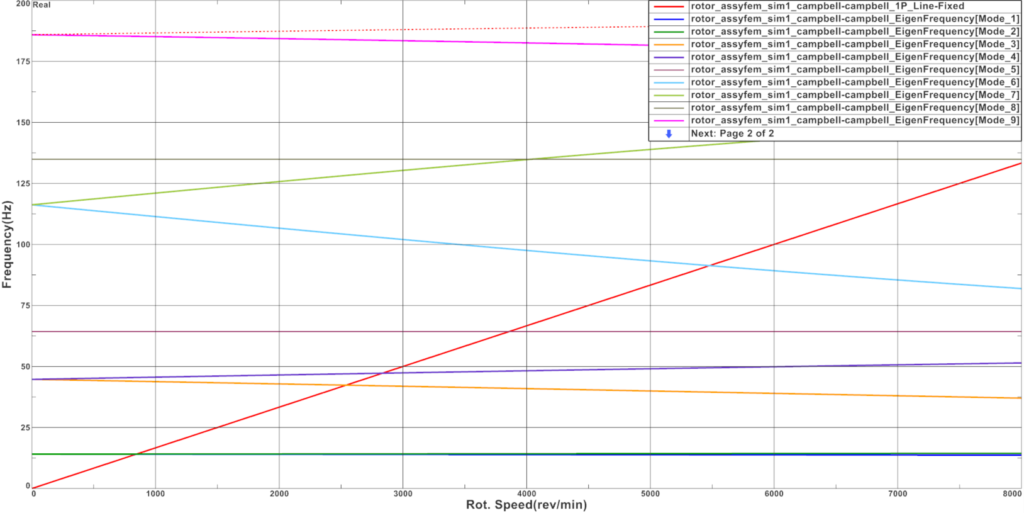
The Campbell diagram for rotor dynamics
An indispensable tool to determine this crucial metric is a Campbell diagram. This one shows how the imaginary part of different eigenfrequencies evolves in function of the rotation speed. After computing a rotor dynamics analysis in the fixed reference frame, you can recognize forward modes as the ones where eigenfrequencies increase with the rotation speed. Eigenfrequencies of backward modes decrease with the rotation speed.
By drawing a first order line, critical speeds can easily be read from the Campbell display.
Keep in mind, besides the rotating structure, also bearings play an important role here, with their specific stiffness, damping and (an)isotropic characteristics. So, also those need to be simulated at highest possible realism.
Moreover, damping in general is an important parameter to a rotating system. Damping inside the structure of the rotating part can have a destabilizing effect to the rotor, particularly above critical speed. On the other hand, damping coming from connection elements or from the non-rotating part has a stabilizing effect. You can analyze this stability on a damping diagram, showing the evolution of the real part of the eigenfrequency as function of the rotation speed. When the real part is positive, the system becomes unstable.
Rotor dynamics forced response analysis
After determining the above dynamic characteristics, rotor dynamics engineers study the impact of external loads or defects. By doing forced response analysis in the time or frequency domain, they can monitor the vibration amplitudes and asses the system’s survivability.
When in the frequency domain, the system is considered in a steady state. If the excitation frequency equals the rotor’s rotation speed, we speak about a synchronous analysis. This is the case for an unbalance or a misalignment load. If the excitation frequency is independent from the rotation speed of the rotor, for example a ground induced vibration, then we speak about an asynchronous analysis. Frequency domain forced response analysis is usually linear, but geometric nonlinearities coming from connection elements can be considered.
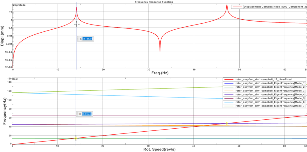
During forced response analysis is when whirling modes become important. Which ones, depends on the case. For example, an unbalance in a rotor mounted on isotropic bearings will excite forward modes only. Those will then cause high vibration levels as the rotation speed approaches the corresponding eigenfrequency. Backward modes do not contribute in this case.
The graph below shows this. The curve represents the displacement amplitude at a rotor disk center as a function of the rotation speed (or frequency, as this is a synchronous analysis). We can see peaks at 14 and 47 Hz. These correspond to the eigenfrequencies of the forward modes, as the Campbell diagram just below indicates. This unbalance phenomenon does not excite backward modes.
Besides frequency domain analysis, rotor dynamics engineers also do forced response analysis in the time domain, or transient analysis. Loads can then be defined as a function of time or rotation speed, to simulate a run-up or a run-down of the system.
Blade-out event
A typical example of where time-domain forced response analysis is necessary is the prediction of a blade out event. During such a simulation, rotor dynamics engineers select a rupture criterion for connection elements and monitor the forces in these elements during transient analysis. When those exceed then a threshold value, the connection breaks and the link between the two connected parts is removed. The example in the video shows a real equivalent of such a simulation, a test on the Rolls Royce Trent 900 jet engine for Airbus A380.
Increasing calculation efficiency using model reduction techniques
Of course, given the safety-critical nature of the work rotor dynamics engineers do, simulation accuracy is of utmost importance. At the same time, computational time and cost need to remain under control. Therefore dedicated model reduction techniques exist, that are especially useful for rotor dynamics.
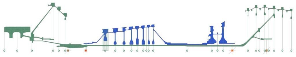
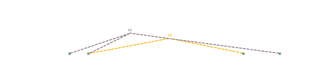
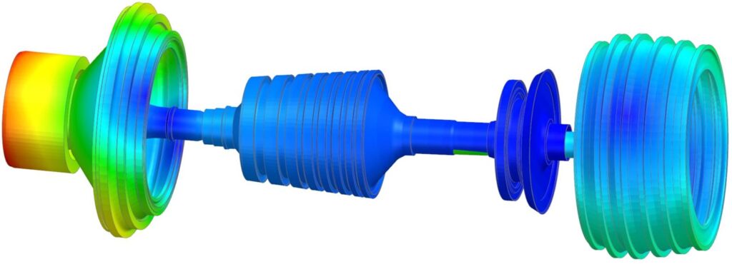
Those use 2D axisymmetric rotors with Fourier harmonics, or superelements which replace the original finite element model by a number of modes and matrices at selected retained nodes. Superelement reduction can take the gyroscopic and Coriolis effects into consideration. So you can replace every rotor of a system by its equivalent reduced model. This technique is utterly interesting to model complex systems that include multiple rotors. Rotors can then be assembled using simple or advanced bearings for linear or nonlinear analyses. During post-processing, methods exist to project the results on the original structure again. This computationally efficient 3-step approach is illustrated with an example below, where 2 connected rotors are simulated.
In summary
Studying rotor dynamics is truly critical to guarantee the survivability or rotating systems. And most of the work needs to happen based on prediction. As the consequences of failure can be dramatic, high-accuracy simulation as you can do in Simcenter 3D for rotor dynamics can save lives. The most important phenomena that can cause damage are rotor unbalance and misalignment. When those occur in combination with the wrong operational conditions, very little is needed to make the entire system unstable.
As described in this blog, rotor dynamics engineers start their analyses by determining the dynamic characteristics of the system in a stationary state. Important metrics are the complex eigenfrequencies and the corresponding whirling modes, as well as the critical speeds, that can be obtained from a Campbell diagram. Next, they study events in frequency-domain and time-domain forced response analysis.
Simcenter 3D includes dedicated tools to complete all the steps in the process. Those include specific functionalities rotor dynamics engineers would need to apply realistic boundary conditions, to effectively prepare geometries and perform meshing, to do more efficient calculations and to get more insightful post-processing.
Related blogs on rotor dynamics
Did you enjoy reading and want to know more? You might consider reading the following blog posts as well:
Rotating systems – tune your intuition
Efficient rotor dynamics for multi-stage turbo machinery
Combine solution speed and accuracy for axisymmetric rotor dynamics


