Bearing modeling makes or breaks rotor dynamics simulation
Hello again, jet engine engineers, turbofan fans and other rotor dynamics disciples!
We are wondering what you were thinking after reading our earlier blog posts on rotor dynamics. The one where newbies can find all the necessary basics to get started with rotor dynamics simulation. Or the other one, where we explain how you can save a massive amount of time by exploiting symmetry.
If you are a bit familiar with rotor dynamics simulation, you probably said to yourself: ‘Well hey, that’s all very interesting, and those tools seem to work really well. But you can still screw up your simulations completely if you haven’t got your bearings modeled properly!’
And that is absolutely a valid remark. Therefore in this blog post, we will elaborate on how you can do accurate bearing modeling in Simcenter 3D for rotor dynamics. We have some in-house solutions, available off the shelf. And we also offer tools by which you can easily leverage your own know-how.
But first, why is bearing modeling so important?
Bearings are the connection elements between the fixed and the rotating parts. So obviously, when studying vibrations in the assembled system, they play an essential role. The flexibility they introduce into the system will affect the gyroscopic effect. But at the same time, you can exploit their damping characteristics during design for stabilization.
So, both to avoid problems/damage and for optimizing the performance of a design, accurate bearing modeling is massively important.
Complex bearing dynamics
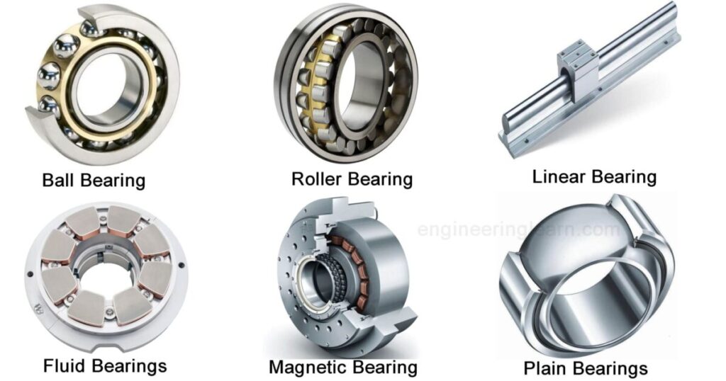
But the mechanical behavior of bearings can be complex. In industrial applications, many include viscous fluid, like oil. Think of hydrodynamic bearings, seals and squeeze film dampers as examples. Other consist of two races that have balls in between them, the so-called rolling bearings (see image below for some examples).
Whatever their composition, in a simulation, bearings bring additional mass, stiffness and damping. And those last two parameters tend to be nonsymmetric, as well as dependent on rotational speed, displacement, or on the velocity of the shaft with respect to the stator. So, clearly nonlinear.
The simplest way to represent them is by 6×6 matrices of mass, stiffness and damping, with coefficients that can be constant or variable, for example with rotational speed.
User-defined bearing modeling
Exactly because of this complexity and strong dependency on operational conditions, many companies have done their homework. They know best how their bearings behave in all possible circumstances. And they have all data available in the form of tables or analytical formulas. Or they use more advanced methods, such as coupling to a fluid code or using external libraries that include bearing behavior.
So how can they leverage this knowledge systematically in rotor dynamics simulations? How can they share this expertise safely within the company, and with partners?
Simcenter 3D for rotor dynamics is the answer
In Simcenter 3D for rotor dynamics, engineers can use their own bearing formulations with limited effort. The software includes Fortran templates, which make it easy to bring the necessary input into the bearing routine, and to define the output so that the rotor dynamics solver gets what it needs.
To illustrate, classic input is partially prepared by the solver. This includes local displacements, velocities and acceleration, the rotation speed, and the current time or the excitation frequency. This comes on top of the external input the bearing law would need to compute the behavior, as well as user input like geometrical data, bearing type, a table of coefficients, or other. As an output to the rotor dynamics solver, the routine typically has to deliver forces, moments and tangent mass, stiffness and damping matrices. It is expected this entire process can be nonlinear and can be included in both harmonic and transient forced response.
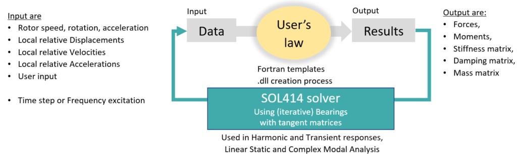
The bearing developer then compiles the Fortran template with a documented procedure to generate a dll, and in this way securely shares the formulation with other users inside the company. End users can simply pick up the formulation when defining a SOL414 analysis.
A little example
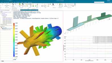
Consider this very simple model of 5 nodes, that combines different bearings, using a simple squeeze film damper formulation in a run-up and run-down nonlinear transient analysis of an unbalance.
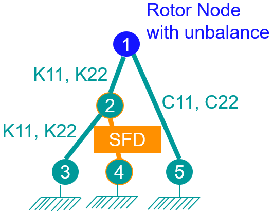
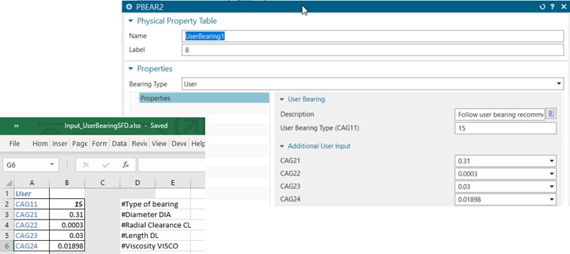
The squeeze film damper formulation is used in the Fortran template. Besides, it also uses input like the viscosity, the diameter of the shaft, the radial clearance and the length of the bearing. And it allows users to set the bearing type, so that can be switched to another formulation when necessary. Input can be prepared in an Excel file and imported in Simcenter 3D.
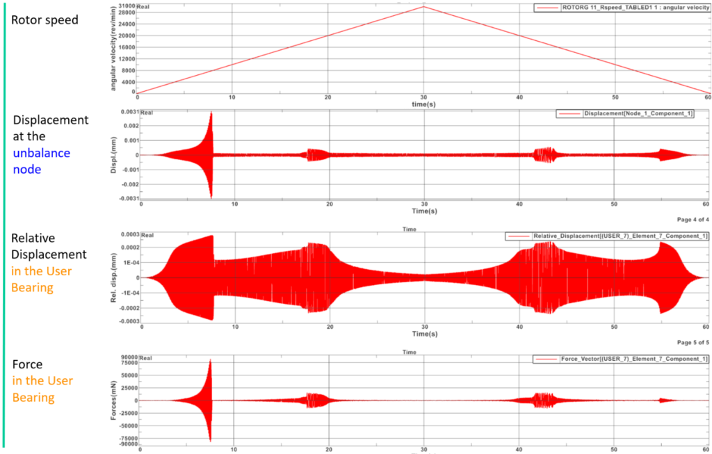
In the image below you can see what happens during the entire run-up/run-down trajectory. During the run-up (first 30 seconds) the rotation speed increases to 30 000 rpm, and then during run-down it decreases in the 30 next seconds. We monitored the displacement results at the location of the unbalance, as well as the relative displacements and forces in the user squeeze film damper. You can see the nonlinearity of the analysis by the fact that results in the last 30 seconds are not symmetric to those in the first 30 seconds.
The Simcenter 3D capabilities for bearing modeling
Of course, besides fully user-defined bearings, Simcenter 3D for rotor dynamics also includes some off-the-shelf solutions for bearing modeling. You can find all of the following connection types:
- Bearings represented by matrices (stiffness, damping, and mass), with constant or variable coefficients (function of rotation speed, excitation frequency, or time)
- Squeeze film dampers, for different configurations in harmonic and transient nonlinear analysis, whose governing equation for pressure is the classic Reynolds lubrication equation with incompressible laminar iso-viscous films.
- Roller element bearings, for different configurations in harmonic and transient nonlinear analysis.
- Hydrodynamic bearings, for different configurations in transient nonlinear analysis, solving 1D Reynolds equations with the short bearing theory.
- Bushings represented by axial or radial properties, including nonlinear functions of elastic forces as function of displacement, and damping forces as function of local velocity. Bushing can also use a damage law to simulate a rupture, to act as a mechanical use, useful in the blade-out event prediction.
- Gear connections (spur gear, bevel gear, helical gear, internal gear)
- Simple springs and dampers
Conclusion
Accurate bearing modeling is crucial for successful rotor dynamics simulation. In Simcenter 3D, you can find numerous connection types to represent your bearings. But most importantly, the software embraces your expertise by allowing you to easily set up user-defined bearing models.
All these capabilities for bearing modeling are available in Simcenter 3D 2021.2.
Related blogs and other information on rotor dynamics
Did you enjoy reading and want to know more? Then you might consider reading the following blog posts and other resources as well: