Smooth vibrations in rotating systems – How to monitor clearance consumption
Clearance Consumption and Clearance analysis
In all turbomachinery applications including pumps, turbochargers, gas turbines, or jet engines, rotating parts and casings are assembled together. OEMs of such turbomachinery applications ensure a minimum gap between the rotational and stationary parts to maximize the performance and efficiency of the application. These gaps are in the order of millimeters on a radius typically many orders of magnitude larger. They need to be controlled and understood to mitigate potential rubbing or damage to the parts.
However, as we discussed in the blog titled: Rotor Dynamics where accuracy is a matter of life and death, defects in the structure and deformation due to the harsh pressure, temperature, or operational loads make the structure vibrate. If these vibrations reach a critical magnitude, the rotor will contact the stator during the rotation cycle. In a transient response observed during the runup of a system, or in harmonic response, as explained in the first blog of this series, engineers want to see what happens during a cycle of the rotating system. Measuring how the clearance is consumed between the rotor and the stator can give important information about the survivability of the system.
In Simcenter 3D Rotor dynamics, engineers can monitor the clearance that is consumed during a cycle, and then, based on an allowed gap compute the Residual Clearance. It provides a straight postprocessing tool that shows any possible contact between the rotor and stator for the critical frequencies.
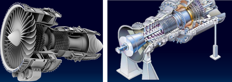
In the picture to the right, the rotor is rotating and vibrating inside the casing, which is also flexible and vibrating. The simultaneous vibrations are both considered during a full cycle and the maximum consumption is computed. If the Residual Clearance remains positive, then the rotor does not come into contact with the stator.
The clearance consumption can be monitored at different locations (compressor or turbine blades) of the structure. The allowed clearance is a user input. It can be the initial cold build clearance measured on the model or determined by the users based on their experience. For instance, an abradable material inside the stator, not represented on the structural model, can influence the allowed clearance during the operations. The engineer can then take this layer of material into account in the allowed clearance, in the form of a time function.
The advantage of this method propose is that the Rotor dynamics solver extracts and displays the most relevant information regarding the consumption of the clearance. This saves the user from postprocessing a lot of data (all vibrations of the stator nodes, vibration of the rotor, over a full cycle, for each frequency, or over a full simulation in the time domain).
Clearance analysis can be studied with 3D rotors as well as reduced models, taking benefit from the axisymmetry of the rotor. Indeed, model reduction approaches presented in our previous blog (Combine solution speed and accuracy for axisymmetric rotor dynamics), such as 1D beam rotor, 2D Fourier multi-harmonic rotor, and super-element can also be used for clearance consumption analysis. Different locations are monitored on the casing and therefore it is consider it as 3D. By coupling this type of analysis with clearance analysis from a whole engine model (see previous blog), the movements from larger 3D structural models (ovality, 3D deformation) and manufacturing tolerances, a clearance engineer can accurately define the clearances of an engine that maximizes performance and efficiency while reducing risk due to rubbing.
Summary
Analysis of defects such as unbalance or misalignment can be studied in a frequency range, but the engineer can also determine the critical speeds and stability of the rotating system. In this blog post, we present how to easily monitor the clearance consumption at specific locations on the full assembly, checking in real time that the rotor and stator do not enter come into contact.
Simcenter 3D includes dedicated tools to complete all the steps in the process. Those include specific functionalities rotor dynamics engineers would need to apply realistic boundary conditions, to effectively prepare geometries and perform meshing, to do more efficient calculations and to get more insightful post-processing