Whole engine modeling for gas turbine performance
English Version
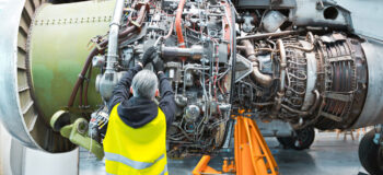
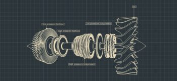
Gas turbine technology has established itself ubiquitously as a reliable and robust power generation and aviation propulsion method. The general operating principle involves sucking air in, compressing it to a higher pressure and temperature using an axial compressor, adding fuel to the compressed air in a combustor and igniting it to produce a high-temperature flow. This high temperature and pressure flow enters a turbine section, producing a rotational work output. Additional components are added to the gas turbine depending on the application. For example, a steam turbine and a generator create a combined-cycle power plant for power generation or a propelling nozzle to produce thrust for flight.
Since the creation of gas turbines, numerous advances have been made to make more powerful and efficient engines. This involved things like using incredibly advanced simulation capabilities to try and understand the highly coupled physics within the gas turbine hot gas path, as well as significant developments in materials (single crystal superalloys, thermal barrier coatings) to ensure that the metal can withstand the ever-increasing and harsh operating environments.
Coupling these engineering challenges with the current migration to green energy, a power generation gas turbine is now frequently used to support green energy sources that depend on favorable weather conditions. This results in more start-and-stops, faster loading and alternative fuels like hydrogen.
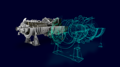
One such development in the field of computational analysis was the creation of a whole engine model (WEM). Depending on the company, this can mean a rotor dynamics model, or in the case I will speak about here, a thermo-mechanical 2D model that represents the complete gas turbine from the compressor bearing to turbine bearings.
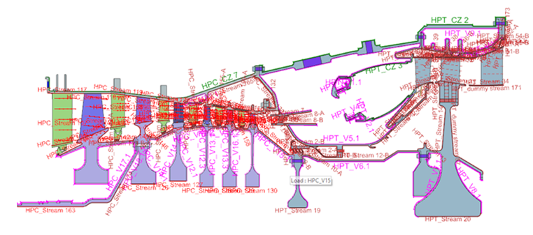
The whole engine model (WEM) is an approach taken within the power generation and aviation industry to model a complete gas turbine through a wide range of operational scenarios. Operational scenarios are defined as the sequence of starting, loading, baseload or cruising operation and de-loading to rundown and rotor barring until the engine is cooled. The thermal state of the engine, especially in power generation gas turbines, dictates when a restart can occur, as rubbing of stationary and non-stationary components can otherwise occur, causing damage to the engine and the subsequent performance.
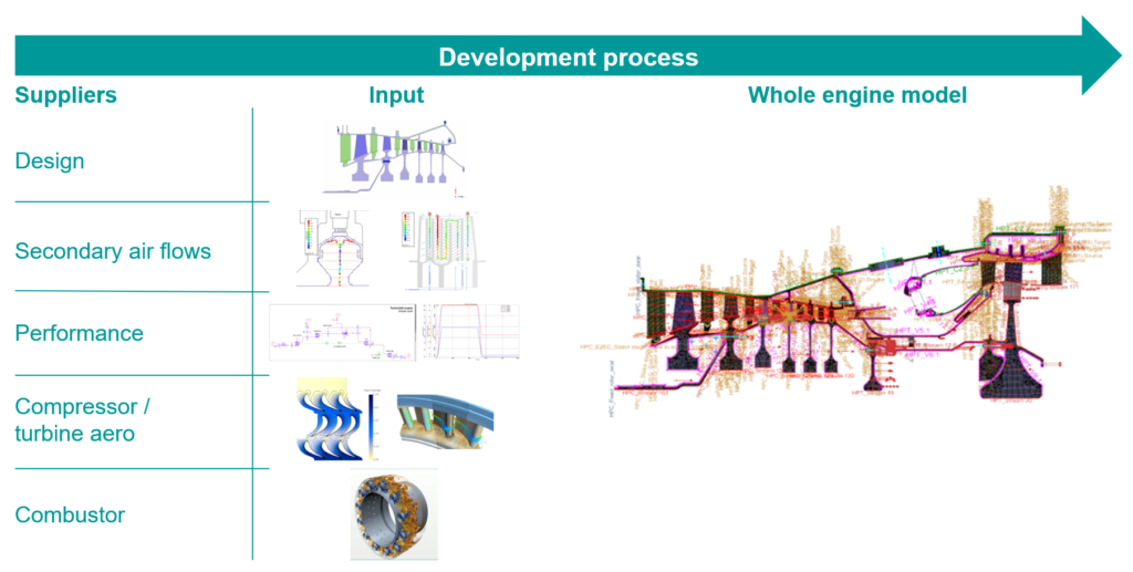
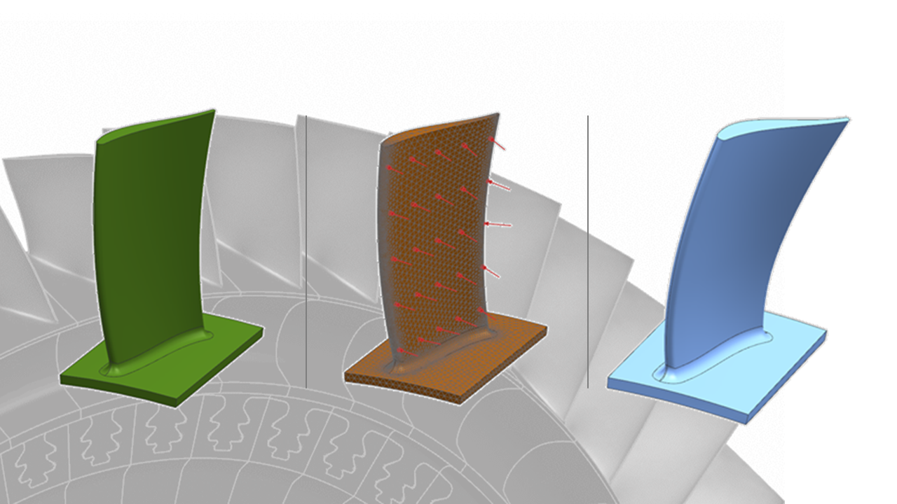
The whole engine model is created by taking the 3D geometry and mapping it onto a 2D plane. Due to the axisymmetric nature of gas turbines, the model is divided into axisymmetric and non-axisymmetric parts. Non-axisymmetric parts are assigned a thickness to account for the differences around the circumference, such as flanges, air extraction ports, blades, and vanes. This typically requires close collaboration between the thermo-mechanical engineer and design engineers of the different components.
Due to the nature of the model, the lead engineer needs to coordinate with all departments to collect input for the model:
- Geometry and materials of the engine – design department
- Cooling flows networks – secondary air flow department
- Operation/mission cycle – performance department
- Aerodynamic loads – turbine and compressor departments
- Cooling flow network and heat transfer coefficients – combustor department
An integral part of the whole engine model are the turbomachinery-specific boundary conditions that model the specific behaviors of the convecting fluid. These boundary conditions can be linked together, creating a 1D flow network that accounts for the flow throughout the engine. The boundary condition inputs allow for both static and rotational frames of reference, while a company’s in-house expertise, which has been developed over the years, can be incorporated into the heat transfer correlation expressions.
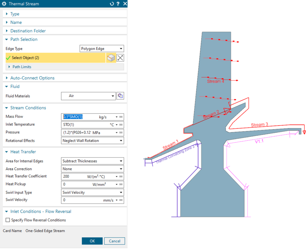
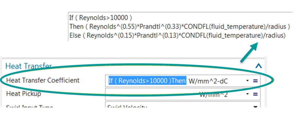
As the main physical parameters of the convecting fluid (pressure, flow rate, temperature) evolve over the engine operation, it is pertinent to account for the changing physics involved – below a certain rotational speed, the flow is not convected through the engine, and this can lead to a different heat transfer process. The whole engine modeling process can account for this in the boundary conditions in two ways:
- Incorporation of if/then statements in boundary condition input fields
- Links to the key parameters from the mission/operational cycle that evolve over time
The culmination of all the boundary conditions and other inputs results in the whole engine model becoming a master model or digital twin of how the complete engine behaves and performs under a range of operational conditions – the results one attains are not just steady state results of one time point, but transient results over the complete mission cycle of the gas turbine engine.
Two key results over the transient cycle are the metal temperatures of the gas turbine components and the clearances – the gaps between the rotating and stationary components.
Gas turbine engineers can understand how the different components in a gas turbine engine interact with each other over range of operational modes, whatever that specific operational cycle is – a normal start up and loading gradient, all the way through to a hot restart or a faster loading cycle. In this regard, the metal temperatures will have a particular thermal behavior which can be used to understand things like mechanical integrity life, or clearance evolution.
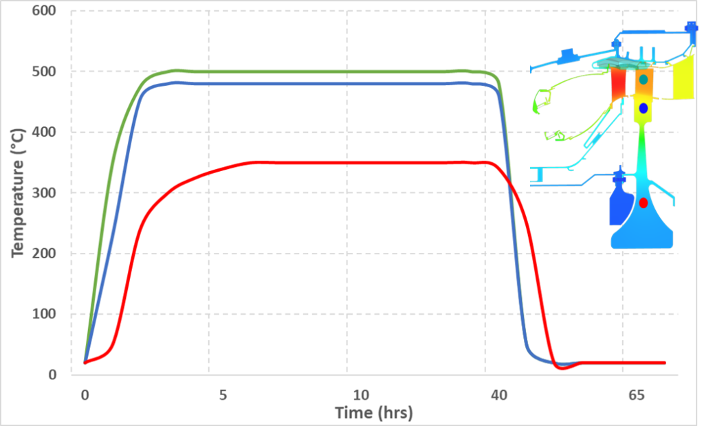
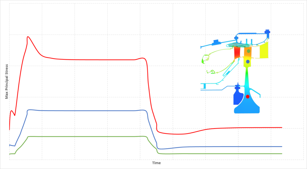
This temperature graph (created for illustrative purposes and is only indicative of a real gas turbine engine) illustrates how the temperature in one blade and disc evolves over a mission cycle. The differences in temperatures are a function of the local heat transfer coefficients as well as the mass distribution. This leads to thermally induced stresses in the metals that can have an impact on metal lifetime, especially significant in mechanically loaded areas like the firtree connections of a blade and rotor. The following graph is an indication of the differences in stresses that can be present in the rotor disc as a result of the temperature differences.
A significant advantage of running a 2D whole engine model is capturing a complete gas turbine’s thermal behavior over any number of potential operational scenarios. Due to both the axisymmetric and non-axisymmetric nature of the geometry, 3D models are expensive computationally and typically slow – utilizing the thermal results of a WEM, the structural team has transient inputs that can be used to identify the mechanical behavior of the various individual components and parts of a gas turbine. Lifetime assessments, 3D deflections and ovality are all things that can be derived from the 3D models and subsequently correlated to the type of operation the gas turbine undergoes.
This additional information on the 3D mechanical movements can then be shared with the clearance team enabling a complete picture of the 2D and 3D clearances – critical information to understand the performance of the gas turbine. Again, this is possible with any range of operational cycles, not just the standard run-up to baseload and shutdown, or in the case of an aero engine the standard take-off, cruise and land cycle.
In the same way that an original equipment manufacturer (OEM) wishes to understand the thermal behavior of the engine, a gap or clearance evolution is also highly desired as it directly impacts the performance of the engine as well as the structural integrity and safe operation of the gas turbine. Simulating the steady state condition of the engine allows one to understand the steady state performance. However, to understand whether rubbing will occur, when it is reasonable to restart a hot engine, etcetera, one needs to simulate the transient start-and-stop of an engine under different conditions.
The following graph is a typical example of how the clearances of one blade may evolve over an operational cycle. An arbitrary cold build clearance is chosen (the gap that exists at the start), and with the application of mechanical and thermal loads we first see the gap between the parts opening and then subsequently closing to a steady state value as the engine reaches a thermal steady-state condition.
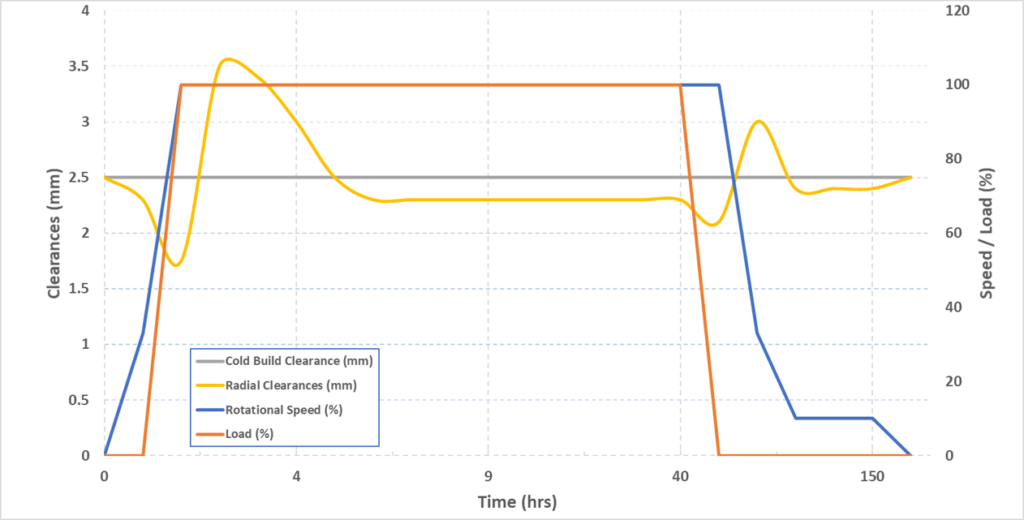
Similarly, at cool down, the gap initially closes more than the steady state due to the cooling of the external casing and then opens again with the reduction of the speed of the engine (no more rotational/mechanical load).
This example is only representative of one blade. The clearance engineer would have to carry out this analysis for each stage to determine the axisymmetric clearance picture of the engine. Subsequently, a complete picture of the clearances can be created by adding in the non-axisymmetric effects like ovality, calculated from a 3D mechanical model, and the manufacturing tolerances and uncertainties. With this information, the balance between risk mitigation and maximum engine performance can be achieved.
In summary, whole engine modeling allows you to understand the transient metal temperatures and clearances within your gas turbine engine over a wide range of operational scenarios. This master model approach enables a company to understand how components interact with each other, optimize the overall performance of a gas turbine and mitigate risks of failure and rubbing while providing mechanical integrity departments with valuable inputs for lifetime assessment. This leads you to a higher-performing engine that functions reliably for longer under more adverse operational conditions.
You might also be interested in…
Webinar
Improving aircraft engine thermo-mechanical performance
Webinar
Speed up the hot to cold blade conversion process
Blog
Thermal fatigue: some hot features in Simcenter 3D Durability


日本語版
ガスタービン技術は、信頼性が高く堅牢な発電/航空宇宙の推進方法として広く確立しています。一般的な動作原理は、「空気を吸い込み、軸流圧縮機で圧縮して圧力と温度を高め、燃焼器内の圧縮空気に燃料を追加し、点火して高温の流れを生成する」というものです。この高温高圧の流れがタービン・セクションに入り、回転出力を生成します。用途に応じて、ガスタービンにコンポーネントを追加します。たとえば、コンバインド・サイクル発電所や、飛行推力を生成する推進ノズルを構築するための蒸気タービンや発電機です。
ガスタービンの発明以来、より強力で効率的なエンジンを作るための多数の進化がありました。たとえば、ガスタービンの高温ガス経路内の高度に結合した物理特性を理解するための先端シミュレーション機能の使用や、金属が過酷な動作環境に耐えられるようにするための材料 (単結晶超合金、遮熱コーティング) の開発などです。
エンジニアリングの課題やグリーン・エネルギーへの移行を背景に、発電ガスタービンは現在、気象条件に依存するグリーン・エネルギー源をサポートするために幅広く使用されています。これが、開始と停止の増加、高速ローディング、水素などの代替燃料につながっています。
数値解析の領域におけるこうした進化の1つが、WEM (Whole Engine Model) の発明でした。企業によっては、これはローター・ダイナミクス・モデル、またはここで説明するケースでは、コンプレッサー・ベアリングからタービン・ベアリングまでの完全なガスタービンを表す熱機械2Dモデルを意味します。

WEM (Whole Engine Model) は、発電および航空業界で採用されているアプローチであり、幅広いオペレーション・シナリオを通じて完全なガスタービンをモデル化します。オペレーション・シナリオは、起動、ロード、ベースロード、巡航オペレーション、デロード、ランダウン、ローター・バーリング、エンジン冷却までのシーケンスとして定義されます。特に発電ガスタービンでは、エンジンの熱状態により、再起動のタイミングが決まります。静止部品と非静止部品の摩擦が発生すると、エンジンが損傷し、その後の性能に影響を与える可能性があるからです。
WEM (Whole Engine Model) は、3D形状を取得して2D平面にマッピングして作成します。ガスタービンの軸対称性により、モデルは軸対称部分と非軸対称部分に分けられます。 非軸対称部分には、フランジ、空気抽出ポート、ブレード、ベーンなど、円周の周囲の違いを考慮して厚さを割り当てます。この作業には、熱機械エンジニアと、さまざまなコンポーネントの設計エンジニアの緊密なコラボレーションが必要です。
モデルの性質上、リード・エンジニアはすべての部門と調整して、モデルのインプットを収集する必要があります。
- エンジンの形状と材料 – 設計部門
- 冷却流ネットワーク – 二次空気流部門
- オペレーション/ミッション・サイクル – 性能部門
- 空力ロード – タービン/コンプレッサー部門
- 冷却流ネットワークと熱伝達係数 – 燃焼器部門

WEM (Whole Engine Model) には、対流流体の挙動をモデル化するターボ機械固有の境界条件が不可欠です。その境界条件を相互にリンクさせて、エンジン全体の流れを表す1D流れネットワークを作成します。境界条件のインプットにより、静的基準系と回転基準系の両方が可能になり、長年にわたって蓄積されてきた社内専門知識を熱伝達相関式に組み込むことができます。

対流流体の主な物理パラメーター (圧力、流量、温度) はエンジン動作中に変化するため、この変化する物理特性を考慮する必要があります。特定の回転速度以下では、流れがエンジンを介して対流せず、異なる熱伝達プロセスにつながる可能性があります。WEM (Whole Engine Model) プロセスは、次の2つの方法により、境界条件でこれを考慮します。
- 境界条件インプット・フィールドへのif/thenステートメントの組み込み
- 時間の経過とともに変化するミッション/オペレーション・サイクルの主要なパラメーターへのリンク

すべての境界条件とその他のインプットの結果により、WEM (Whole Engine Model) は、「さまざまなオペレーション条件下で完全なエンジンがどのように動作し、機能するのか」を示すマスターモデルまたはデジタルツインとなります。単に一時点の定常状態の結果だけでなく、ガスタービン・エンジンのミッション・サイクル全体の過渡状態の結果が得られます。
過渡サイクルの2つの重要な結果は、ガスタービン・コンポーネントの金属温度と、クリアランス (回転コンポーネントと固定コンポーネントの間のギャップ) です。

ガスタービン・エンジニアは、ガスタービン・エンジンのさまざまなコンポーネントが、多様なオペレーション・モードで (通常の起動からローディングの勾配、ホット・リスタート、高速ローディング・サイクルまで、どんなオペレーション・サイクルでも) どのように相互作用するのかを理解できます。これに関して、金属温度は、機械的完全性の寿命やクリアランスの変化などを理解するために使う熱挙動を持ちます。
この温度グラフ (説明のために作成した、実際のガスタービン・エンジンの参考値) は、1つのブレード/ディスクの温度がミッション・サイクルを通してどのように変化していくのかを示しています。温度の違いは、質量分布と局所的な熱伝達係数の関数です。これは、金属の寿命に影響を与える可能性のある金属の熱誘起応力につながり、特にブレードとローターのファーツリー接続などの機械的に負荷がかかる領域で大きくなります。次のグラフは、温度差の結果としてローター・ディスクに存在する可能性のある応力の違いを示しています。

2D WEM (Whole Engine Model) を実行する大きな利点は、可能性のあるあらゆるオペレーション・シナリオを通して完全なガスタービンの熱挙動を取得できることです。形状の軸対称性と非軸対称性の両方により、3Dモデルは計算コストが高く、通常は低速です。構造チームは、WEMの熱結果を利用して、ガスタービンのさまざまなコンポーネントと部品の機械的挙動を識別するために使う過渡インプットを持っています。寿命評価、3Dたわみ、楕円度はすべて、3Dモデルから導き出すことができ、その後、ガスタービンが受けるオペレーションのタイプと相関させることができます。
3D機械動作に関するこの追加情報をクリアランス・チームと共有して、ガスタービンの性能を理解するための重要な情報である2Dおよび3Dクリアランスの全体像を構築することができます。繰り返しになりますが、これは、ベースロードやシャットダウンへの標準的な準備だけでなく (航空エンジンの場合は標準の離陸、巡航、着陸サイクルだけでなく)、あらゆる範囲のオペレーション・サイクルで可能です。
相手先ブランド供給 (OEM) はエンジンの熱挙動と同様に、ギャップまたはクリアランスの変化も理解したいはずです。エンジンの性能だけでなく、ガスタービンの構造的完全性と安全なオペレーションにも直接影響するからです。エンジンの定常状態をシミュレーションすることで、定常状態の性能を把握することができます。しかし、摩擦が発生するかどうかを理解するには、高温のエンジンを再起動するのが妥当な場合など、さまざまな条件下でエンジンの過渡的な開始と停止をシミュレーションする必要があります。
次のグラフは、1つのブレードのクリアランスがオペレーション・サイクルを通してどのように変化するのかを示す典型的な例です。任意のコールド・ビルド・クリアラン ス (開始時に存在するギャップ) を選択し、機械的負荷と熱負荷を加えると、最初に部品間のギャップが開き、エンジンが熱定常状態に達すると定常状態の値にまで閉じます。

同様にクールダウン時には、外部ケーシングの冷却により、ギャップは最初、定常状態よりも大きく閉じ、その後、エンジン速度が低下する (回転/機械的負荷がなくなる) と再び開きます。
この例は、1つのブレードのみを表しています。クリアランス・エンジニアは、エンジンの軸対称クリアランスの全体像を決定するために、各段階でこの解析を実行する必要があります。その後、3D機械モデルから計算した楕円率などの非軸対称効果、および製造公差と不確実性を追加することで、クリアランスの全体像を作成できます。この情報を使用して、リスクの軽減と最大のエンジン性能のバランスを実現することができます。
要約すると、エンジン全体をモデリングすることにより、幅広いオペレーション・シナリオでガスタービン・エンジン内の金属の過渡温度とクリアランスを理解できます。このマスター・モデル・アプローチにより、コンポーネントが互いにどのように相互作用するのかを理解してガスタービンの全体的な性能を最適化し、故障や摩擦のリスクを軽減すると同時に、機械的完全性部門に寿命評価のための貴重なインプットを提供することが可能になります。これにより、より過酷なオペレーション条件下でより長く安定的に機能する高性能エンジンが実現します。
こちらもいかがですか。
ウェビナー
航空機エンジンの熱機械性能を向上させる
ウェビナー
ホットブレードからコールド・ブレードへの変換プロセスを高速化
ブログ
熱疲労: Simcenter 3D Durabilityのホットな機能