Log in
Skip to content
Main Navigation
Blogs
Products
All Products
Additive Manufacturing Software
Aprisa
Calibre IC Design & Manufacturing
Capital
Catchbook
Custom IC
Designcenter
Digital Logistics
EDA Consulting Services
Electronic Systems Design
Fibersim
Hardware Assisted Verification
HLS Design & Verification Blog
Insights Hub
JT
Mendix
NX Design
NX Manufacturing
Opcenter
Pave360
PLM Components
Polarion
Questa
Semiconductor Packaging
Service Lifecycle Management
Simcenter
Solid Edge
Teamcenter
Teamcenter Manufacturing
Tecnomatix
Tessent Solutions
Valor
Industries
All Industries
Aerospace & Defense
Automotive & Transportation
Consumer Products & Retail
Electronics & Semiconductors
Energy & Utilities
Heavy Equipment
Industrial Machinery
Marine
Medical Devices & Pharmaceuticals
Podcasts
All Podcasts
3D IC
Additive Manufacturing Podcast
AI Spectrum
Bugged Out
Cloud Talk Today
Digital Powers Flexible: Consumer Products Podcast
Digital Transformation Podcast
Empowering Engineering Educators
Energy Transformation Podcast
Engineer Innovation Podcast
Engineering the Future Workforce
Model Based Matters
Next Generation Design Podcast
On the Move: A Siemens Automotive Podcast
Pioneers: Startups from Dreams to Reality
Printed Circuit Podcast
Security by Design
Talking Aerospace Today Podcast
The Battery Podcast
The Digital Dig - A Siemens Heavy Equipment Podcast
The Industry Forward Podcast
The Marine Industry Podcast Series
The Voice of Smart Digital Manufacturing Podcast
Where Today Meets Tomorrow Podcast
German only Podcasts
Machinenbau Talk
Thought Leadership
All Thought Leadership
Digital Transformation
Embedded Software
Expert Insights
Simulating the Real World
The Art of the Possible
Thought Leadership
Verification Horizons
Corporate
All Corporate
Academic and Future Workforce
AWS Partnership
Corporate Blog
Cre8Ventures (Siemens EDA)
EDA Support Blogs
Employee Spotlight
Partners
Realize LIVE
Siemens Xcelerator Academy
Siemens Xcelerator Software for Industry
Small & Medium Business
Xcelerator for Startups Videos
Community
Home
All Thought Leadership
Jim Wright
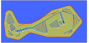
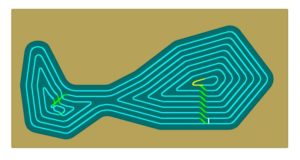
2D Nesting – More Than You Ever Wanted to Know
July 2, 2019
The Solid Edge 2020 portfolio has expanded again with a new manufacturing product - Solid Edge 2D Nesting. Before we get into the details of the product, I want to spend a moment explaining the...
By wrightj
< 1
MIN READ
How can design for manufacturing solve problems before they occur?
April 24, 2019
It’s not quite reverse engineering, however design for manufacturing or design for manufacturing and assembly puts into consideration the cost of manufacturing a product, or a series of products, and...
By wrightj
< 1
MIN READ
In-Process Workpiece in Solid Edge CAM Pro
October 17, 2018
In-Process Workpiece (IPW) is a great feature that Solid Edge CAM Pro provides to show the state of the machined model during the machining process. If you don't understand why that is valuable...
By wrightj
< 1
MIN READ
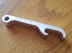
CAD, CAM and Beyond – Seminar #1 from IMTS
September 21, 2018
IMTS was a huge success. AMT (the organization that runs IMTS) says there were almost 130,000 attendees and over 2100 booths and both those numbers were new records. You can read the full...
By wrightj
< 1
MIN READ
Benefits of a Solid Edge CAM Pro Bundle
September 10, 2018
bun-dle; noun - a collection of things, or a quantity of material, tied or wrapped up together. Software is often sold in bundles, and we are no exception to the rule. Over time, in...
By wrightj
< 1
MIN READ
Feature Based Machining in Solid Edge CAM Pro
August 30, 2018
I was a machinist and CNC Programmer long before I started to work for Siemens. Working in a job shop, we developed a saying – “Parts are parts”. Hey, I didn’t say it was a clever saying....
By wrightj
< 1
MIN READ
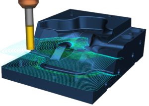
Adaptive Machining in Solid Edge CAM Pro
August 23, 2018
A few years back, I wrote a 3-part blog post on “The Evolution of Tool Path Design”. If you haven’t read Part 1, Part 2, and Part 3, they are still valid today. Go ahead, I’ll wait. &nb...
By wrightj
< 1
MIN READ
What’s New in Solid Edge CAM Pro
August 15, 2018
In a previous blog post, we introduced you to Solid Edge CAM Pro. Now, we can talk about What’s New in the product. For clarity, I will be referring to some features from a previous relea...
By wrightj
< 1
MIN READ
Introducing Solid Edge CAM Pro
August 7, 2018
Siemens is excited to announce Solid Edge CAM Pro. Formerly known as CAM Express, Solid Edge CAM Pro is the perfect CAM companion to Solid Edge. Solid Edge CAM Pro is built on the powerfu...
By wrightj
< 1
MIN READ
Teach an Old (CAM) Dog New (CAD) Tricks
September 25, 2017
I know CAM. In fact, it's fair to say that when someone within the Solid Edge organization has a CAM question, they probably end up talking to me. But for CAD?Let's just say I'm not first on a...
By wrightj
< 1
MIN READ
The Process of 3D Printing
April 6, 2015
If you haven't seen my previous posts on this topic, they are here, here, and here. Now that I have some experience with 3D Printing, I can lay out the process in more detail. First,...
By wrightj
< 1
MIN READ
3D Printing a Solid Edge Design
March 23, 2015
If you haven't seen my previous posts on this topic, they are here and here. Now that I have some experience using the 3D Printer, I need to step up my game and design something for i...
By wrightj
< 1
MIN READ
My First 3D Print – Teddy Roosevelt
March 16, 2015
If you wish to read my previous post on this topic, look here. It’s here! My AirWolf 3D model HD printer has arrived. I unboxed it (following all printed instructions and a hel...
By wrightj
< 1
MIN READ
From NC Pro to 3D Printer Novice
March 9, 2015
I am a machinist and CNC Programmer, and I like to refer to myself a “CAMologist”. My entire professional career has revolved around subtractive processes. I don’t use the word “expe...
By wrightj
< 1
MIN READ
Machining Multiple Parts on 4-axis Tombstone with CAMWorks for Solid Edge
June 3, 2014
In my last post, I mentioned that job shops like to be efficient. Efficiency in production operations means more profits for the shop. One way to increase efficiency is to reduce the numb...
By wrightj
< 1
MIN READ
Machining Multiple Setups with CAMWorks for Solid Edge
May 29, 2014
Job shops like it when they get to produce more than one of the same item. It lets them amortize their setup costs over several parts, rather than just one. They REALLY like it when they ...
By wrightj
< 1
MIN READ
Mill-Turn Capability in CAMWorks for Solid Edge
April 24, 2014
CAMWorks for Solid Edge not only supports traditional turning, but it also supports mill-turn machines (aka multi-function machines). A typical mill-turn machine can perform traditional turning...
By wrightj
< 1
MIN READ
CAMWorks TechDB
April 22, 2014
CAMWorks for Solid Edge does a great job of automated machining of prismatic geometry. With Automated Feature Recognition (AFR), features of various sizes and shapes are recognized for machinin...
By wrightj
< 1
MIN READ
Using CAMWorks for Solid Edge
April 10, 2014
I want to use this post to address the basic operation of CAMWorks for Solid Edge. At its core the product uses built-in intelligence to recognize several different types of prismatic features ...
By wrightj
< 1
MIN READ
CAMWorks for Solid Edge Introduction
April 8, 2014
Today is the beginning of a series of posts about CAMWorks for Solid Edge, which is an embedded CAM product that runs entirely within Solid Edge. It was developed by the good folks at Geometric...
By wrightj
< 1
MIN READ
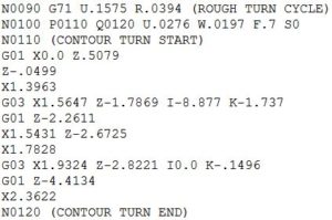
G71 Lathe Roughing Cycle
February 18, 2014
I recently received a request to demonstrate how to create a G70/71 lathe roughing cycle in our Post Builder product. Our CAM Development team created CYCLE95 (lathe roughing for Siemens contro...
By wrightj
< 1
MIN READ
Create Stock Body from Design Body
February 4, 2014
When a job shop receives the 3D model of a part to be machined, they seldom receive a 3D model of the raw stock (or stock body). For most situations, that’s not a problem, because there are sev...
By wrightj
< 1
MIN READ
NX9 CAM Interactive Cut Regions
January 14, 2014
Interactive Cut Region management is a new tool added to NX9 to help CAM users easily segregate “steep” from “non-steep” areas*. This new capability means that the overall NC programming proces...
By wrightj
< 1
MIN READ
NX9 CAM “Notes” Enhancement
December 3, 2013
My last blog post was about the Description field enhancement. Now I want to cover its companion, Notes. Notes give the NC programmer an easy-to-use capability to convey information direc...
By wrightj
< 1
MIN READ
Description Field Enhancement in NX9 CAM
November 26, 2013
In each release of NX, there are always enhancements that are overlooked and underappreciated. I think the enhancements made to Notes and Description fields in NX9 CAM fit into this category. ...
By wrightj
< 1
MIN READ
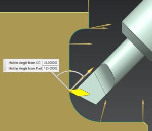
Tilt Tool Axis
October 29, 2013
I showed in a previous blog post how to use Divide By Holder to keep the cutting tool as short as possible. Today I want to show how to take advantage of multi-axis capability of NX CAM and CAM...
By wrightj
< 1
MIN READ
Pencil Milling Part 2
September 25, 2013
In this post, I want to explain some of the options for working with Flow Cut. I find that new users consistently struggle with understanding some of these options. First up is Max...
By wrightj
< 1
MIN READ
Pencil Milling Part 1
September 20, 2013
“Pencil Milling” is the name given to a machining strategy where a small-diameter ball end mill is used to perform finish milling in small nooks and crannies of a complex mold or die. The word ...
By wrightj
< 1
MIN READ
Machining Steep and Non-steep Geometry (Part 2)
September 13, 2013
In my last post, I showed several wrong ways to machine steep and non-steep geometry. In this post, I will show a method that is better. NX CAM can scrutinize a model and determine...
By wrightj
< 1
MIN READ
Machining Steep and Non-steep Geometry
September 11, 2013
Several years ago, I hiked into the Grand Canyon. I spent a couple of months training my body for the trip. I loaded up my backpack with 45 lbs. (about 20 kg) of material, and hiked 3-5 m...
By wrightj
< 1
MIN READ
Tool Path Divide
September 4, 2013
If you really want to scare an NC programmer, just show them a deep, narrow cavity on your latest design, and then comment that you must have a mirror-like surface finish at the bottom. ...
By wrightj
< 1
MIN READ
Roughing and Re-roughing
August 30, 2013
In NX CAM we refer to a specific set of machining instructions as an operation. For example, finish-milling a planar face would be one operation. To spotdrill, drill, and bore a hole requ...
By wrightj
< 1
MIN READ
The Evolution of Tool Path Design (Part 3)
August 27, 2013
In this post, I will explain the latest tool path innovations for removing large quantities of material.I mentioned in Part 2 that Offset tool paths have problems when the offsets meet at shar...
By wrightj
< 1
MIN READ
The Evolution of Tool Path Design (Part 2)
August 22, 2013
In Part 1, I covered Zig and Zig-Zag tool paths.In Part 2, I take a look at Offset tool paths. To achieve complete cutting in odd-shaped areas, Offset tool paths were developed. ...
By wrightj
< 1
MIN READ
The Evolution of Tool Path Design (Part 1)
August 19, 2013
The primary purpose of modern Computer Aided Machining (CAM) programs is to create efficient tool paths for Computer Numerical Control (CNC) machining. Since machining is a subtractive process, ...
By wrightj
< 1
MIN READ
Evolution of Tool Paths
April 5, 2013
How did tool paths get this complicated? This article traces the roots of tool paths evolution. The primary purpose of modern Computer Aided Machining (CAM) programs is to create eff...
By wrightj
< 1
MIN READ