Teach an Old (CAM) Dog New (CAD) Tricks
I know CAM. In fact, it’s fair to say that when someone within the Solid Edge organization has a CAM question, they probably end up talking to me. But for CAD?Let’s just say I’m not first on anyone’s speed dial. So, when I use a CAD system, I like easy.Easy to figure out, and easy to use.I think Solid Edge fits that bill.
A couple of weeks ago, I walked into my shop.Well, more like stumbled into it.It is a disorganized mess.The main problem is I don’t have enough storage for my tools.How to solve this problem?Hey, I know – I’ll build a cabinet!6 ft. (1.8 meters) tall X 4 ft. (1.2 meters) wide X 2ft. (.6 meters) deep should hold a lot of tools, right?I chose those dimensions, because a standard sheet of plywood in the U.S. is 8 ft. X 4 ft. – the first sheet gives me the back of the cabinet and the top (or a shelf).
So, I fired up Solid Edge ST10 and began designing.First I created the back sheet (really simple to create a rectangle by 2 points and then extrude it).I dimensioned the sketch before extruding, but a true modeling pro would probably have put the dimension on after extrusion (Synchronous Technology allows you to work either way).
Step two -> New Assembly of Active Model.In less than a minute I had an assembly with one component. Then I hit the Create Part in Place button and sketched/extruded one of the sides.Save the assembly, then bring the just-modeled side panel from the Parts Library back into the assembly for the opposite cabinet wall.
From then on, it was just a repeat of Create Part in Place/Parts Library drag and drop.I did Assembly Relationships as I brought each component in.Here’s the finished model. Cabinet as Designed
Next, I wanted to find out how many sheets of plywood I would need.I created a new assembly and sketched outlines of plywood, then began the drag and drop nesting process.I did this manually and it was easy to do, but having some automated nesting algorithm to do it would have been nice. Nested Layout
My analysis showed I would need slightly more than 3 sheets to build this cabinet.I wanted the local lumberyard to make the cuts for me, so I created a drawing of the cut layout and dimensioned it.Here’s where my lack of drafting experience failed me.I know that it is possible to dimension using traditional U.S. fractional sizes (1/8, 1/4, 1/2, etc.), but I couldn’t figure out how to quickly change it, so I just left the dimensions as decimal. This became slighlty problematic at the lumberyard, because I then had to convert decimal to fractions on the fly to help out the person running the saw.But, we got the job done and no one lost any fingers.
 Drawing of Cut Layout
I wanted to see a more realistic view of what the cabinet would look like, so I did a quick render in Keyshot.Again, this was really easy.If I can do it, anyone can. I even figured out how to use my drawing as the backdrop for the rendered image. Rendered Cabinet in Keyshot
It took a couple of evenings to assemble the cabinet.I added some braces under the shelves and top that weren’t in the orginal design.Then I painted it…and painted it…and painted it.Do you have any idea how much paint plywood will absorb?Wow.
 Finished Cabinet
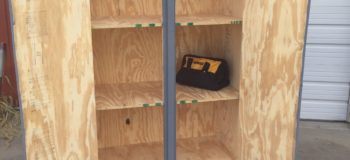
Handles, hinges and latches completed the job.In my area of the world, we have a lot of Mud Daubers that would love to build nests in a fine cabinet like this, but I’m happy to report that it is bug-tight and insect free. Interior of Cabinet
What’s next for me?I don’t know – maybe I’ll design a dumpster so I throw away some of the junk that is still in my shop.![]()
What design project is next for you?


Comments