The Evolution of Tool Path Design (Part 2)
In Part 1, I covered Zig and Zig-Zag tool paths.In Part 2, I take a look at Offset tool paths.
To achieve complete cutting in odd-shaped areas, Offset tool paths were developed. These are created by calculating an offset (usually a percentage of the cutting tool diameter) from the area to be cut.Then, an offset is calculated from that offset and so on until the entire area is cut.
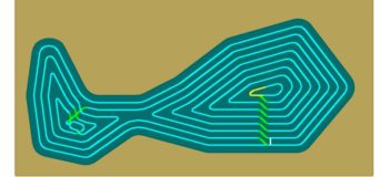
Below is an example of an offset tool path combined with Zig-Zag (Zig-Zag first and then offset paths to clean up walls). At first, these new tool paths were used to clean up geometry left over from the Zig/Zig-Zag cuts.

Eventually, the technology developed to completely mill an irregular shape using only offset part tool paths.

Offset tool paths are very efficient at covering the entire area to be machined, but they create a problem for manufacturing engineers at the point where two offsets converge at a sharp angle.

The problem is the tool becomes completely embedded in the cut (100% engaged/full width of cutter). That means the feedrate must be slowed down, and there is a tremendous amount of stress put on the cutting tool, which could lead to breakage.This video shows the full width engagement:
Adding radii at the sharp corners can help, but often you have to make the passes closer together just to assure no material is left between the passes in the acute corners.

In my next blog post, I will explore more advanced tool path strategies.
Thanks for reading.