Feature Based Machining in Solid Edge CAM Pro
I was a machinist and CNC Programmer long before I started to work for Siemens. Working in a job shop, we developed a saying – “Parts are parts”. Hey, I didn’t say it was a clever saying. What we meant by that was this: we didn’t care about the ultimate usage of the part we were currently machining. We cared about how to get that part efficiently machined. Aerospace, Automotive, Consumer Products, meh. If the Consumer Product part we were machining looked like an Automotive part that we had machined before, we used the techniques we developed for Automotive to create tool paths on it. The industry didn’t matter to us.
So, when I look at a model for potential machining, I mentally classify it by geometry. Is it prismatic (all surfaces parallel or perpendicular to tool axis), or swarfy-swoopy (contoured geometry)?  Prismatic
 Swarfy-swoopy
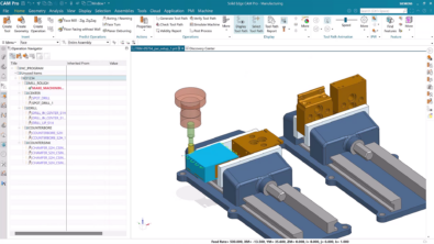
I look at other things too (part rigidity, part material, tolerances, etc.), but the geometry classification comes first. Prismatic geometry is easier and quicker to machine, and therefore less expensive. One of the reasons that is true is because we can use Feature Based Machining methods (FBM) to create the tool paths.
Most of our CAM competitors that have FBM lead with it – they want to start with FBM and then tackle the non-prismatic features of the model. Solid Edge CAM Pro presents FBM as another tool in the toolbox – you can use it if you like, but you can also completely ignore it and do everything manually.
There are a couple of things that I really like about our FBM:
1. You can now use an existing operation set as the template for machining a set of features. This means you don’t have to learn how to edit the knowledge base.
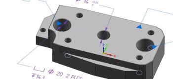
2. Product Manufacturing Information (PMI) is taken into account. For example, on this model I transferred from Solid Edge to Solid Edge CAM Pro, the middle hole size is 14mm +.25/-0. FBM chose a 14.1mm drill (closest one in the library to the middle of the tolerance zone). That is Model-Based Definition (MBD) at work in a downstream application. Pretty cool stuff. 
If you’re attending IMTS, why not stop by booth 134500, East Building and see us? You can get a live demo of both Solid Edge and Solid Edge CAM Pro.We will also be showing off some live machining.