Gas Turbine CFD – Driving Innovation with Data and Insight
Once upon a time in a world without gas turbine CFD simulation.
Manager: The design team came up with a new blade concept, but they need to know the maximum possible temperature in the machine.
Test engineer: Anywhere in the whole machine?
Manager: Yes. And for any operating condition the machine might get used for. How long until you can have those results to the team?
Test engineer: Uhh…
Terms like “virtual prototype”, “simulation testbed” and “digital twin” have become so common that you may dismiss them as buzzwords. However, to me, these terms not only still have meaning. These words do drive how I look at simulation.
You can dismiss the “digital twin” as a buzzword. But that won’t solve your problem.
As with other engineering methods, the goal of using simulation as a digital twin is to improve a product or process. But using a digital twin has a distinct advantage as compared with other engineering methods such as physical tests. Simulation is able inform design improvement based on the underlying physics of how and where a piece of machinery is operating in a way that would be too expensive, too time consuming, or just plain impossible to do with the physical machine.
Additionally, it’s often possible to gain more insight than with a physical machine. A digital twin offers the ability to know things like the temperature and pressure of materials everywhere in space not just where there happens to be a measurement probe. It offers the ability to shrink down and take a virtual-reality firsthand look inside the machine as it’s operating. It offers the ability to run the machine at any operating condition, no matter how dangerous that may be in real life.
Delivering on this unique potential for innovation requires two main ingredients: reliable data and meaningful insight.
The power of data
Good decisions must be informed decisions. Informed by reliable data. In the world of engineering simulation, obtaining vast amounts of reliable data is only possible when using a digital twin platform that has all the necessary elements: accurate physics, real-world geometry and a streamlined process.
Physics
Simcenter STAR-CCM+ has been laser focused on building models to accurately capture the physics of gas turbine engines. From inlet to exhaust, it is possible to simulate the real-world flow, chemistry and heat transfer of these complex machines. Incorporating these physical models into the same simulation results in fewer engineering assumptions and greater realism, ultimately leading to more robust, reliable and innovative designs. Several articles explore state-of-the-art physics modeling for gas turbine CFD.
Geometry
What good are the most accurate physics models if you overly simplified the geometry? World-class automated meshing of full-complexity geometry is a required first step in producing a digital twin that can produce the reliable data needed to drive innovation. The geometry handing and meshing process within Simcenter STAR-CCM+ can capture the intricate details of the real-world geometry with a high-quality mesh so that the data produced is meaningful and reliable.
- Clearing the path to innovation through next generation parallel polyhedral mesher
- Whistle while you mesh: Simcenter STAR-CCM+ model-driven adaptive mesh refinement (AMR)
- Topology optimization – CFD creating designs like nature
Process
With the ability to accurately model the physics of a full-complexity gas turbine engine, a useful digital twin must be able to produce data quickly and reliably without the need for expert tuning so that insight is provided early enough to impact design.
Simcenter STAR-CCM+ is truly unique in its ability to streamline the simulation process. This ability stems from built-in process automation for shortening overall time and effort required.
With an automated process in place, now it’s time to get greedy! Now you can produce ridiculous amounts of data from basic design sweeps to optimization and sensitivity analysis studies.
- From design exploration to design thinking in 100s of simulations
- Unlock the power of CFD simulation and go from 1 to 100s!
With all of this, the stage is set to generate accurate data using gas turbine CFD…and lots of it. Let’s take a look at how a new boundary condition option is going to help in our quest for data.
Speed-up the speedline with gas turbine CFD
With every release, Simcenter STAR-CCM+ continues to advance what it is possible to simulate in gas turbines as well as simplifying that process. With the goal of producing meaningful data as quickly as possible in mind, we added the Outlet Corrected Mass Flow option.
Compressors must operate through a range of different conditions and one of the most important metrics engineers use to evaluate compressor performance is the speedline. This simple plot describes how much pressure the compressor can produce at the outlet as compared to how much air passes through it. Additionally, the extents of the plot provide key insight. The right extreme of the plot lets a designer know the maximum possible air through a compressor, known as choke. The left extreme gives the maximum pressure ratio after which there would be a catastrophic flow reversal through the machine, known as surge.
The right boundary condition? Choose wisely!
When deciding how to model a compressor system, one important choice to make is what type of boundary conditions should be used. Typically, we know the total pressure at the inlet, so that is a great condition to specify there. But what should be set at the outlet? It is common to set either the static pressure or the mass flow at the outlet. However, each of these boundary conditions can only reliably map out one side of the curve or the other. As a result, engineers often watch the speedline generate and manually intervene to change the boundary conditions while moving from choke to surge. This is slow and inefficient.
The video below illustrates how using the new corrected mass flow condition at the outlet simplifies the simulation process and produces more meaningful data. The new option is appropriate for all portions of the speedline, does a better job mapping out the surge and choke extents of the curve, and provides a uniform distribution of points along the entire length of the curve.
Innovation from insight
Reliable data is necessary, but not sufficient for generating innovative designs. It must also be possible to extract meaningful insight from the data. There is a spectrum of data analysis that engineers can use to answer questions about a given design. One end of the spectrum is reporting global performance metrics as single values. This includes quantities such the efficiency or pressure ratio of a machine. On the other end of the spectrum we find hyper-localized data such as the temperature at a specific location at a specific instance in time. The middle of the spectrum requires more nuance because the data must be synthesized to show meaning in the raw data. Two improvements with Simcenter STAR-CCM+ 2021.1 focus on needs for analyzing turbomachinery CFD results in this middle ground.
Circumferential average of gas turbine CFD results
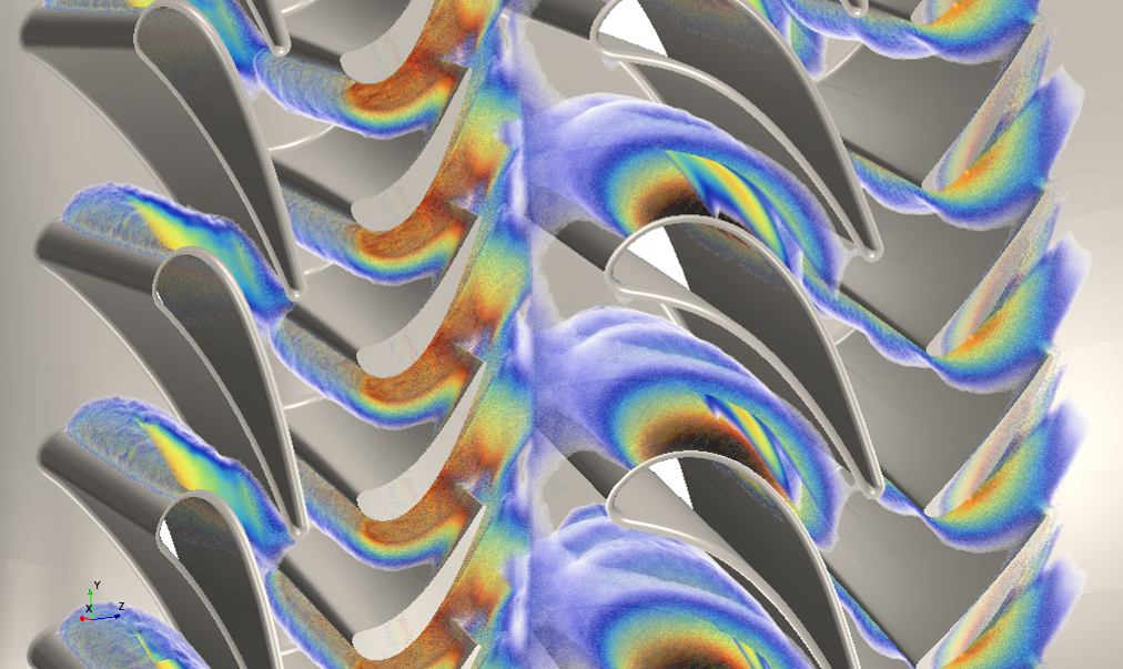
Averaging the solution around the axis of the machine reduces a huge data set into a two-dimensional solution that can quickly provide insight to macroscopic trends. The video below shows how it is possible to take a full 3D solution and quickly visualize the average solution on a 2D plane.
This is an example of how synthesizing the data can provide more meaningful insight. Imagine for a moment that you are trying to determine if there is separation on the hub or shroud surfaces of this turbine. In both images shown below, the flow moves from left to right and blue contours indicate low axial velocity. The image on the left shows axial velocity everywhere in the turbine. The right image shows the circumferentially-averaged solution. In which image can you see the main flow structures more clearly? Is it more obvious in the image on the right that there is separation on the hub?
Local flow solution 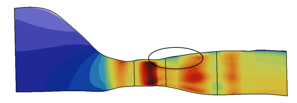
Average flow solution
This data analysis method allows engineers to interpret a full-complexity solution more easily and compare back to the intended design of a machine. The gas turbine’s design process progresses through higher and higher levels of fidelity. Relating full-complexity CFD results back to simpler design methods such as 2D through-flow analysis is of critical importance. This closes the design loop and allows for the accurate CFD model to directly inform design decisions.
Blade-to-blade section embedding for gas turbine CFD
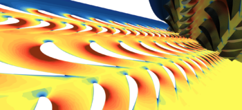
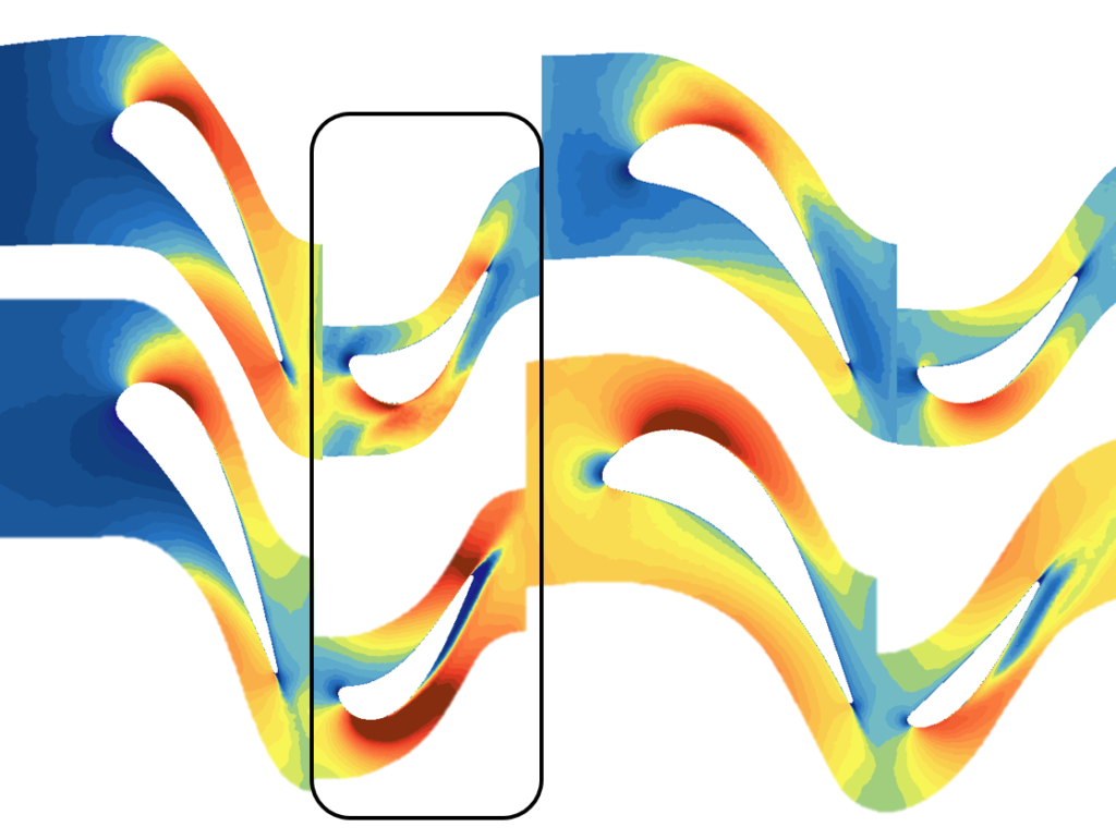
Another common and important data analysis tool in turbomachinery is the blade-to-blade view. This is a surface-of-revolution about the machine axis at a percent distance from hub to shroud. Because the flow-path can be complicated, this blade-to-blade section is not a simple cylinder. Visualizing the flow solution at these specific sections is much easier to understand if the section is flattened out or embedded into the plane. This is typically done with something called an 𝑚′− 𝜃 (pronounced m prime theta) transformation.
Having a flattened view offers two main benefits. First, it is easier to view the solution everywhere in the domain without the need to manually move around the machine. This makes the information more consumable. It is much easier to understand the flow field at a glance. Second, having this standardized view allows for more meaningful comparisons between different section locations and different designs. The pair of images below compares the axial velocity on two different blade-to-blade sections. Having this flattened, standardized view allows for differences to be observed more easily. We can see the separation present in row 2 of the lower section indicating a redesign may be necessary.
Building a digital twin, not a digital somewhat similar
Enabling innovation in gas turbines through CFD has been and will remain a focus for Simcenter STAR-CCM+. We will continue to execute on our vision of delivering a true digital twin by incorporating key elements like no other platform can: physics, geometry, process, exploration and insight.
It starts with a geometry and meshing process that does not require simplification of the geometry. After all, we are building a digital twin, not a digital somewhat similar. For physics, Simcenter STAR-CCM+ models the most complex processes from surge to combustion to turbine heat transfer. The platform has been designed to wring every drop of data out of that digital twin by minimizing the time it takes to get a result and by enabling thousands of variants to be analyzed. Finally, we are focused on giving turbomachinery experts the data analysis tools they need to be able to extract insight from the data with specialized methods.
We have come a long way so far, but you should rest assured that we will not rest. Our turbomachinery simulation roadmap is filled with new capabilities in every area from aero-performance focused meshing, to thermoacoustics analysis, to structural assessment, to even more data analysis capabilities.
Want to learn more? Listen in to our turbine webinar on 10 March. We’ll demonstrate:
- how to set up and run example cases,
- hints and tips on how to speed up your turbine simulations,
- an overview of our roadmap for future turbomachinery capabilities
The future of gas turbine development is now
Manager: The design team came up with a new blade concept, but they need to know the maximum possible temperature in the machine.
Test engineer: Anywhere in the whole machine?
Manager: Yes. And for any operating condition the machine might get used for. How long until you can have those results to the team?
Simulation engineer: Cool, gimme a few days. What else do you need?
Test engineer: Happy to back you up. At your disposal for validation!
Manager: Thanks, guys!
It is exciting times to see all the advancements coming to gas turbine simulation and even more exciting to see what is being done with these capabilities.


