Turbomachinery CFD simulation: art in motion
Believe it or not, there is some true art in turbomachinery CFD simulation. From the creamer in your coffee, to the tumbling of flow through a small waterway. There is something palpable with intrigue when observing fluid flows in our everyday routines. As computational fluid dynamics practitioners, we are fortunate to have a unique opportunity. That is to simulate and observe these same curious fundamentals of turbulence and fluid flow until our heart is content.
The beauty of turbulence – painted by turbomachinery CFD simulation
In the realm of turbomachinery, there is no shortage of diversity in the types of flow structures and turbulent mixing. “Thanks” to their complexity, turbomachines like gas turbines involve plenty of beautiful flow phenomena. In fact, now the stakes have been raised – energy content is being added into and extracted from the flow and the resulting turbulent structures are not only taken for a ride, but precisely manipulated to maximize the performance of the system. For example, consider the cooling flow which is meant to blanket and protect the blade surface, as in the media below. The turbulence between the primary flow and the blanket of cooling flow streams has a massive impact on the effectiveness in shielding the metal parts from high heat loads. And they are just beautiful pieces of art to look at!
Likewise, one can enjoy the Mach number distribution in the compressor stage of an axial turbomachine. Andy Warhol would be proud of turbomachinery CFD simulation.
So, in the name of all things turbulent, let us turn our attention to some noteworthy flow structures in turbomachinery in more detail! And, frankly, these are just enthralling to look at (and no, this will not include The Starry Night).
Flap in the gap
Now let’s ask ourselves what kind of environment are these turbulent eddies operating in? Begin to imagine the immense loading on these blades and vanes. Let’s, simplistically, equate the blade to a one foot long cantilevered body. The equivalent loading from the flow could be on the order of several fully-grown elephants sitting on the edge!
Furthermore, the local flow on either side of the blade can experience pressure differences of several times the atmospheres on earth!
This causes the flow to pass from one side of the blade to the other, by passing over the blade tip. Unfortunately, this results in a serious hit in performance. So how do we prevent this from happening? We need a careful design of the blade tip. This is a balancing act between a small and a big gap between the rotating blade tip and the stationary shroud. Too small and it causes wear and tear from rubbing of the rotating blade on the stationary shroud. Too big and it can lead to poor aerodynamic performance.
Understanding and manipulating the flow and turbulence of this tip flow is paramount to the success of this balancing act.
Turbomachinery CFD simulation reveals the devil in the details…
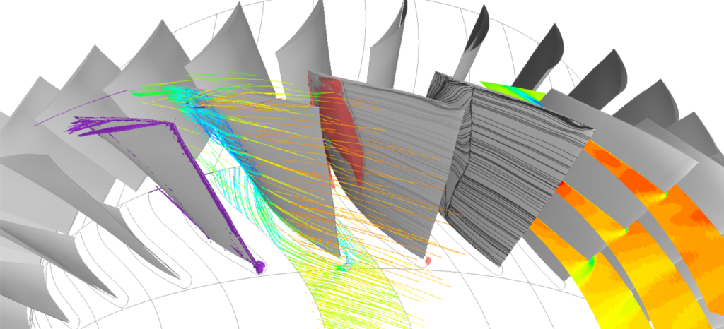
Let’s take a look at this turbulence in action to gain more insight. The picture above shows a compressor stage of an axial turbomachine. Streaklines on the blade surface show the local orientation of the flow as a result of the turbulent structures present. Those influence the separation and reattachment. The iso-surface traces where the flow is locally reversed and heading upstream. It makes clear we are looking into a complex flow-field with lots of turbulence. Traces of reversed flow are apparent in the vicinity of the tip, and appear coherent! Note the high streamline curvature of the flow in the aft region, and sharp breaks with an immediate separation front.
As the flow squeezes through the passage between the blade tip and the shroud, the transport of heat via the turbulence is also an important interest. Large and/or unexpected temperature gradients can be detrimental to the hot section turbine hardware components. For the compressor, the thermal expansion is also an important consideration to ensure an optimal gap size.
This complex ‘smearing’ of the thermal inertia is a challenge to predict. Thermal energy from the flow interacts with the shroud and within the vicinity of strong rotational forces.
… and the devil inside
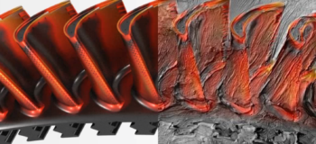
Let’s make our way inside the blade now to take a look at the work our secondary flows are doing. This is to ensure our metal temperatures are in a safe range while in operation. After all, the hot gas path temperature can be hundreds of degrees hotter than the melting temperature of the hardware components. Yes, hundreds, you read that correctly. Therefore, winding serpentine channels with protruding rib turbulators inside the blade are typically used to augment heat transfer. Furthermore, the flow can discharge throughout a number of locations around the blade, whereby exiting as an impinging jet, a film cool, a tip leakage flow, or a trailing edge slot flow, to name a few.
Accuracy is key in this scenario! Elevated levels of cooling from these secondary flows usually come with a penalty of higher pressure drops. The latter essentially ‘steals’ potential power output from the entire machine.
One turbomachinery CFD simulation? Why, if I could do 100s!
Now imagine, you had the capability to let your CFD software generate designs that meet all of your requirements while providing large strides in performance!
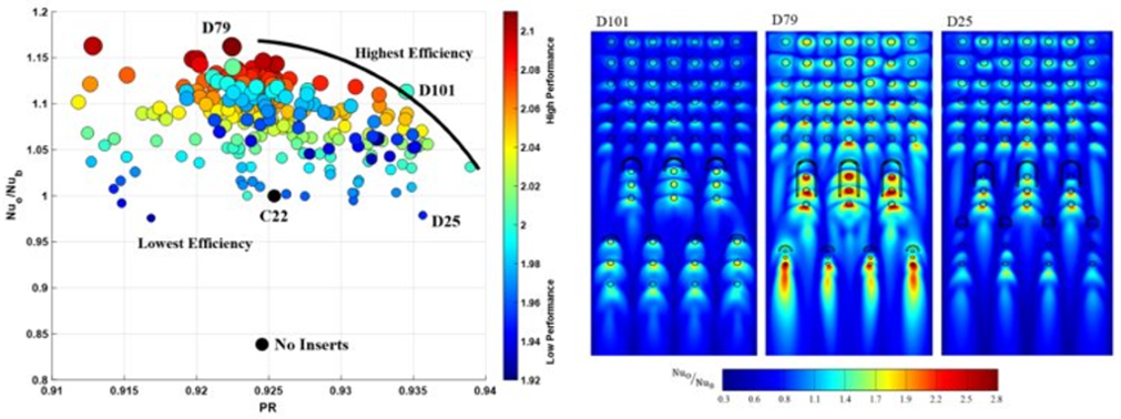
Pictured above, we can see this in action for a large cooling channel which is curved and shaped in a manner that is similar to a gas turbine blade leading edge. This channel has an array of impinging jets located over the surface for the sake of providing significant cooling, just like in field operation. Leveraging CFD and design exploration, the authors manipulate not only the jet size and array pattern, but also the shape and position of obstacles located throughout the cooled surface in order to break-up the flow structures and provide augmented heat transfer rates (cooling). While generating the complex configurations for optimal cooling, such is done with care to minimize the resulting pressure drop required to pump the cooling jets into the channel.
This study landed a 129% increase in cooling while preserving the pressure drop!
Simcenter STAR-CCM+ is built for turbomachinery CFD simulation with ease
The abovementioned flow details on the blade tip are just the tip of the iceberg. And while this complexity causes a lot of beauty, it also adds the requirement for a powerful CFD solution to engineer better turbomachinery. Therefore, we have made Simcenter STAR-CCM+ to conduct turbomachinery CFD simulation with ease. Handling complex geometries and delivering a high-fidelity digital twin of any turbomachine, it allows you to make accurate temperature predictions. And with the release of Simcenter STAR-CCM+ 2020.2 you can now further boost accurate thermal predictions on the casing. With proper averaging amid the rotating and stationary components.
Being able to accurately model these advanced flow physics, such as the tip flows in compressor and turbine designs, takes simulation fidelity to the next level with ease. And it’s just beautiful to look at.
So, why don’t you become a master of art in motion? Download Simcenter STAR-CCM+ today!


