Topology optimization – CFD creating designs like nature
It’s this time of the year that I get to go away with my family and enjoy vacations in my favorite place in the world. A tiny little island in the Aegean Sea where you can lose yourself enjoying the sun, the sea and the endless Greek blue sky (not to mention the amazing Greek food!). This year we needed to escape more than ever. With lockdown, home schooling and the added stress of a pandemic, this little isolated gem felt like true “heaven on earth”.
As I am sitting in a café enjoying a freddo cappuccino, I look at the bay. There is no wind, so the sea is very slowly moving in and out, eternally chiseling the rocks and the sand of the beach. Years of this dance of nature resulted in this stunning little sandy beach, enclosed in the bay.
Can we use maths and physics to create organic designs like nature?
Humans have been trying to understand and explain nature for thousands of years. We invented maths to solve the laws of physics that describe nature. Computational Fluid Dynamics has come a long way. Today, engineers widely use CFD in predicting behaviors of systems without the need for a physical model. Furthermore, parametric optimization allows you to improve the behavior of those simulated systems.
But can we use maths and physics to create organic designs like nature? Can we start from a handful of requirements on the flow and thermal aspects and let maths generate a completely new and optimum design? With the advances of Additive Manufacturing we have the tools, and freedom, to go create truly organic looking shapes! But, how do you design them in the first place?
Topology optimization and Generative engineering
The solution is there and, as with so many things, mathematics holds the key: Adjoint! One can use this mathematical method to obtain the sensitivities of a cost function from a physical problem that is governed by the Navier Stokes equations. You can use those sensitivities to solve a gradient optimization problem driving shape or topological changes of the design. We call this adjoint topology optimization – an integral part of generative engineering.
For running an adjoint topology optimization you merely need to start from the envelop in which your design will be located. This is naturally giving you the spacing constraints satisfaction. The method will chisel away all the parts of your geometry that hinder the set cost function characteristics. It is turning them into solid and defining the shape that allows the optimal flow path. Just like nature!
Adjoint topology optimization has gained a lot of traction in recent years, especially with the advances in additive manufacturing. Siemens and HP together demonstrated how we can effectively use a combination of Adjoint topology optimization within Simcenter STAR-CCM+, design tools of Simcenter 3D, like NX, and HP Jet Fusion printing to create a new version of an HP printer cooling duct. The resulting part became famous as the “Mighty Duct” , achieving a 22% flow increase to the system as a result.
The evolution of Adjoint topology optimization in Simcenter STAR-CCM+
In Simcenter STAR-CCM+ 2019.2 we released a new adjoint solver to serve as the basis for continuous improvements.
In Simcenter STAR-CCM+ 2020.3, inspired by the success but also the hurdles of the “Mighty Duct” project, we are introducing an integrated solution for fluid/thermal adjoint based topology optimization. Streamlined and easy to setup, the Topology Optimization feature mitigates any need for complicated JAVA macros or third-party tools. It features an integrated constrained optimization method. This allows you to solve engineering problems with competing attributes. By defining one objective and multiple flow and thermal constraints as well as volume constraint it offers numerous possibilities.
The topology optimization method is based on a level set approach. Unlike the traditional porosity method this approach is not just blocking the flow from the cells with source terms. It is rather defining a moving interface around the predicted flow path.
And, this has various advantages! Getting a cleaner interface between solid and fluid which results in designs with less kinks and folds. Eliminating the spare pockets of flow that the porosity method creates. This significantly reduces the clean-up and CAD reproduction time and ultimately reducing the cost of production. The level set approach further improves the robustness of the optimization solutions. This allows users to run with semi-converged adjoint and flow solutions for the intermediate step. Additionally, since the interface is clearly defined, one can apply treatments for turbulence and the fictitious solid surrounding the design. One of those treatments is adaptive mesh refinement of the fluid/solid interface.
Aircraft engine fuel injector – the unconventional way
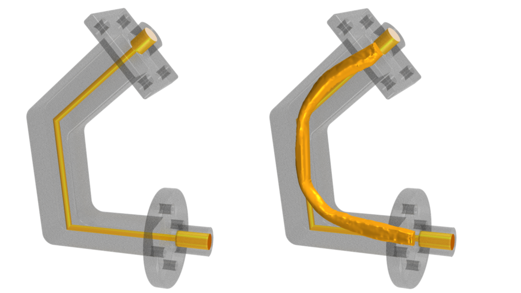
So, we took it to the test with a component of a simple fuel injector for an aircraft engine. Here we are interested in a lightweight and sleek design. It should not contain too much fuel which might cause issues with entrapped gas. And it should have an improved performance in terms of more steady flow and less power consumption for the pump. Traditional shape optimization methods cannot take advantage of the full envelop. They really only explore a vast design space as they are restricted by the original shape and the parameterization itself. In this case we have quite a large envelop to work with. This allows the new design to achieve amazing performance improvement, as the video below shows.
A pressure drop optimization with volume constraint (for that light weight design) wielded the required results. Within less that 5 hours for setup and run (2h optimization time in 10 cores) we improved the pressure drop of the system almost 10 times!
Redesigning the cooling duct of an automotive battery pack with topology optimization
Electrification in automotive is currently a hot topic of discussion. Electric vehicle batteries are continuously improving delivering more power and having greater autonomy but one of the biggest challenges that remain is battery safety and the ability to design an effective cooling system. The cooling system needs to be able to keep the battery in a specified temperature range as well as keep the temperature differences wihin the battery pack to a minimum. EDAG as mobility engineering experts are exploring, with the help of Siemens, the use of additive manufacturing and topology optimization for designing an optimized battery pack water cooling system which maintains those properties.
An inlet duct leading to a spiral piping structure and ending with an outlet duct forms the cooling system. The inlet duct needs to split the massflow equally into three channels each one supplying a separate cooling circuit. The outlet duct then unifies those 3 streams into one channel.
We are interested in increasing the mass flow at the inlet duct for a given head pressure and improve the pressure drop of the outlet duct in order to ensure the increased mass flow can be transported through the entire system. All of this is serving the higher goal to get as much coolant as possible to the battery. We tackle this by a two step optimization. One for the inlet and one for the outlet duct.
Employing the new Topology optimization method we achieved a 6.4% increase in the mass flow of the inlet duct and 46.9% reduction in the pressure drop of the outlet duct. All this in just 2 days of simulation time (~50 hours in 336 cores). See the video for the amazing new organic design.
Smart complementary features
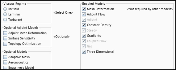
But we did not stop at the surface. In order to support the Topology Optimization feature, we added a dedicated Optional Adjoint Models selector in the Physics models improving the user journey for adjoint related applications.
Furthermore, in order to assist our users to extract the optimized design at the end of the topology optimization we introduced a new closed iso-surface derived part. This feature significantly reduces the manual steps a user must take to get a new, smoothed part as a result of the optimization. A closed iso-surface from the fluid domain and the remaining wall after finalizing the topology optimization run makes it possible.
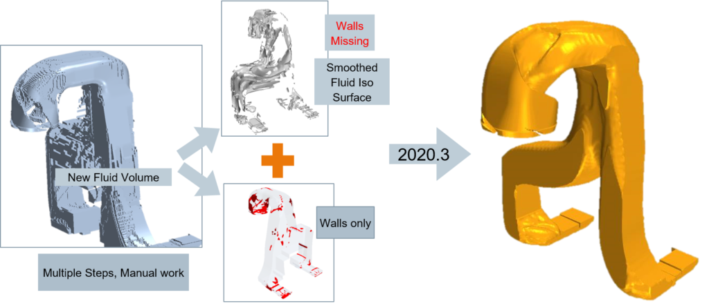
The part can be meshed and used to validate the optimum design. Ultimately, it can be imported in NX and create a new CAD part ready for printing.
The end of this story and the beginning a new reality

As I am sitting here, enjoying the view and finishing my coffee, I feel sad that in a week or so I will have to leave this beautiful holiday place and go back home. On the other hand, with generative engineering, employing mathematics, physics and topology optimization to create seamlessly beautiful, organic, optimum designs, (just like nature!) engineers will never have to go back to traditional methods of design!