Vibrations in Rotating Systems – When defects and harsh conditions break the symmetry of rotating systems
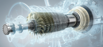
Rotating systems such as Gas Turbines are used for power generation in the energy industry, or propulsion in the aerospace industry and are subjected to harsh conditions with high temperatures and loads. Under such stress, defects induced during the manufacturing process can have catastrophic effects on the performance of a part. When there is an imbalance in the external loading or when internal imperfections affect the symmetry of the system, vibrations can occur that, depending on the rotational speed and intrinsic characteristics of the system, damage part or the whole assembly. we discussed this previously in our blog titled – Containing Aircraft Engine Failure.
The thermal deformation (thermal bow) of a turbomachine appears in the presence of a vertical temperature gradient, induced by the cooling process after a shutdown of the engine. When the engine restarts, the rotor bow can be responsible for high vibrations in the engine and must be studied carefully. Bow can also be due to static forces or pressure.
In such a system we can expect vibrations when the structure deforms due to temperature and static load. but vibrations of each rotating part can also be due to its imperfections, such as an eccentricity of the centre of mass of a bladed disk.
Moreover, many rotating systems are made of different components which do not rotate at the same speed. For example, in a gas turbine, the high-pressure turbine and compressor stages can rotate three times faster than the low-pressure turbine and compressor stages. We must then understand how rotating speed-dependent defects will be taken into account in harmonic response.
In this blog post, we address two important scenarios in harmonic response: the dynamic unbalance induced by a deformed shape (thermal bow), and multiple unbalances on different rotating parts.
When thermal and static deformation induce vibrations of a rotating structure
Rotating systems often experience harsh conditions of temperature, pressure, or loads that might create vibrations of the system. In an earlier blog, we presented how the dynamics can be affected by defects in the rotor due to manufacturing, like the non-uniform distribution of mass or a misalignment of the shaft. In this blog, we see how the external conditions causing rotor deformation will influence the vibrational behaviour of the system.
The bow shape induced by the thermal bow deforms the structure making it asymmetric about the rotor axis. This deformation moves the mass so that it is no longer uniformly distributed around the rotor axis. The eccentricities with respect to the rotor axis induce unbalanced loads that are proportional to the square of the rotation speed.
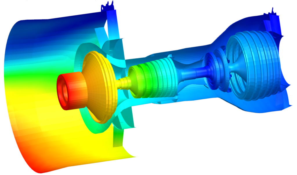
In the above example (1), a rotating system is made of two rotors: the High-Pressure rotor rotates 3 times faster than the Low-Pressure rotor. The system is modelled by 2D Fourier elements (axisymmetric model with Fourier harmonics), which is the best alternative to 3D models, in terms of accuracy and CPU time, as we presented in an earlier Blog Post. External conditions are such that a static force deforms the rotors in the form of a bow. (2) The bow shape breaks the symmetry of the rotor around the rotation axis. Consequently, it naturally induces an imbalance on both rotors that is equal to:
Mass x ecc x Ω2
Where Ω is the rotor speed of each rotor and ecc is the eccentricity deduced from the deformed shape. Those unbalances on both rotors cause vibrations in the whole system that can be studied in the operating frequency ranges, to ensure that levels of vibrations are acceptable. Vibrations are represented for a selected frequency and selected harmonic in (3), and orbit plot in (4) can reproduce the total vibration of the system for a selected location and frequency. We will address later in this blog how the software can manage unbalanced loads that correspond to different rotation speeds.
Imperfections in the rotating parts induce undesirable loads in the rotating system
Initial defects coming from the manufacturing process are independent of the external loading on the structure. However, they induce loads in the structure that result in vibrations of the structure. Among the typical scenarios in rotor dynamics that require testing, the simulation of unbalanced defects is the top priority for engineers. An unbalanced defect occurs when the mass and geometric centres do not coincide. Unbalance creates a load that is amplified with the rotor’s rotation speed Ω, proportionally to Ω2.
In the clip below, the unbalanced rotating system mounted on flexible bearings can show very high vibration amplitudes when the system rotates, especially for certain rotation speeds. The peaks in the response correspond to the unwanted critical speeds of the system. In an earlier blog, we showed how to identify the critical speeds of a system that uses real bearings.
Multiple harmonics in frequency response
In an assembly made of many rotors rotating at different speeds, multiple unbalanced defects can exist where each induces forces that are linked to different rotational speeds, and subsequently different frequencies.
When studying the harmonic response, engineers are interested in the behaviour of the system for one full cycle, in a range of frequencies (or rotation speeds), as discussed previously.
With a single defect, the equation of motion is solved for a single frequency ω:
or by defining the dynamic stiffness matrix
Z(Ωω)q(ω)=g(ω)
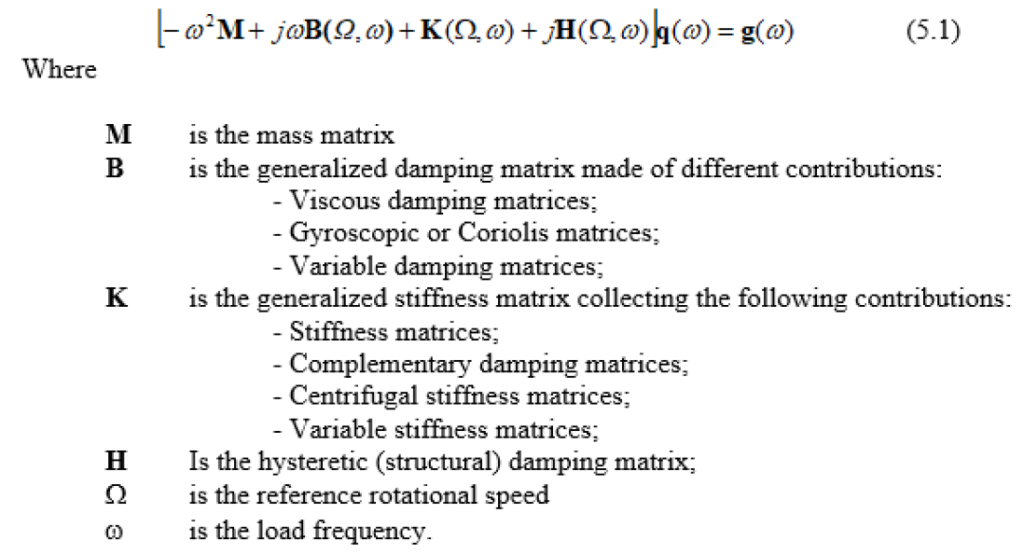
Now, for multiple defects corresponding to different rotation speeds, Simcenter 3D Rotor Dynamics uses multiple harmonics simultaneously to solve the simulation. Each harmonic corresponds to the individual frequency (rotation speed) of each rotor.
Equation (5.1) becomes a system of equations to be solved, for different frequencies ω.
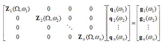
Equations of the system are not coupled when the rotors are axisymmetric so the whole assembly can be solved in a fixed reference frame, with the bearings’ behavior represented by linear functions.
In a simulation using multiple harmonics, results are output for each individual harmonics ω1, ω2,… , making postprocessing less intuitive compared to the mono-harmonic case.
Fortunately, it is possible to recombine results of all harmonics in the time domain through orbit plots for one or several cycles to display the final result.
In the example of the dual rotors, where the unbalances were deduced from the deformed shape, two harmonics (ω1 and ω2) were used according to the two rotor speeds Ω1 for the low-pressure rotor, and Ω2=3Ω1 for the high-pressure rotor.
For each reference frequency, the result for the displacement in the Y direction for harmonics ω1 and ω2 are shown in the picture below.

Having identified the peak of displacements at ω1=55 Hz, we can check the total vibration by combining the two harmonics for the Displacement in the X and Y directions (perpendicular to the rotor axis):
X (t) = Xω1* e i (w1 t + φ1) + Xω2 * e i (w2 t + φ2)
Y (t) = Yω1* e i (w1 t + φ1) + Yω2 * e i (w2 t + φ2)
Where (Xω1, Yω1) and (Xω2, Yω2) are the vibrations computed in the harmonic 1 and 2 respectively. A point on a rotor axis that is linked to a high-pressure rotor can be represented with an orbit plot (X(t), Y(t)). Where, one period at the reference frequency of the first (low pressure) rotor corresponds to 3 cycles of the second (high pressure) rotor:
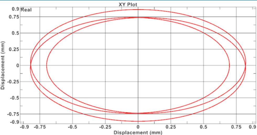
With such an orbit plot, the engineer can determine if the vibration in the operating frequency range is acceptable. A demo of how this can be done in Simcenter 3D is shown below.
In Summary
With harmonic response, the engineer has the possibility to study the behavior of their rotating system in a range of frequencies and rotation speeds. With such analysis, defects like unbalance or misalignment can be studied in a frequency range, and external loads can be applied as a function of frequency.
In this blog post, we presented how Simcenter 3D Rotor Dynamics can study simultaneous unbalance defects on different rotors rotating at different speeds, but also the natural unbalance that can be deduced from a deformed geometry (thermal bow or static bow) due to external factors such as applied loads and temperature.
Simcenter 3D streamlines the complete workflow from the definition of the geometry to the post-processing tools and includes dedicated tools to complete all the steps in the process.
Related blogs on rotor dynamics
Did you enjoy reading this blog and want to know more? You may also like the following blog posts:
Rotating systems – tune your intuition
Efficient rotor dynamics for multi-stage turbo machinery
Containing aircraft engine failure
Combine solution speed and accuracy for axisymmetric rotor dynamics
Bearing modeling makes or breaks rotor dynamics simulation
Multi stage cyclic symmetry in rotor dynamics
Advances in resonance and cyclic symmetry of bladed rotor assemblies
Identify the peaks of harmonic response during operation of nonlinear rotor dynamics
Smooth vibrations in rotating systems – How to monitor clearance consumption