The future of thermal design – earlier electrothermal analysis
I attended a panel discussion several years ago at the SEMI-THERM Thermal Technologies Workshop about the ‘Future of Thermal Design’. One of the speakers imagined a future where (paraphrased) “Electrical spice files and thermal spice files could be used together for early concurrent electrothermal system design”. My interpretation of that statement remains that going forward, electrical and thermal systems must be designed as one whenever possible, as continuing to work in electrical and thermal silos would begin to carry more and more inefficiencies, errors, re-work and risk.
Circuit simulation and thermal design: What are Boundary Condition Independent Reduced Order Models?
At the time of the conference mentioned above, an electrical-thermal-spice workflow was simply not practical in a general sense. While thermal spice files do indeed exist, unlike electrical spice files, they can only be created for use in a single, fixed, thermal environment. It’s important to note that until only recently, no method had been identified to create a thermal spice file with a known accuracy at any operating power cycle, or even to support multiple heat sources in a device. The introduction of the thermal netlist export from Simcenter Flotherm 2020.1 (described here) solved the accuracy and multi-heat source problem, but the single thermal environment limitation remained until Boundary Condition Reduced Order Models (BCI-ROM) technology was released at Simcenter Flotherm 2020.2.
Simcenter Flotherm leverages the FANTASTIC1 method to export Boundary Condition Independent Reduced Order Models (BCI-ROMs). These are exportable for electrothermal modeling in the IEEE Standard 1076.1 VHDL-AMS format, making it compatible with many functional schematic circuit simulation tools. The BCI part of the name is critically important. It means the model will retain accuracy in any thermal environment. It is a realization of the accurate, portable, version of the future ‘thermal spice file’ envisaged by the conference speakers phrase at the start of this blog.
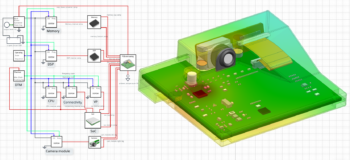
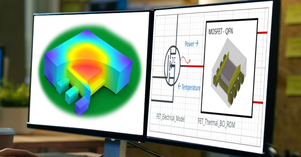
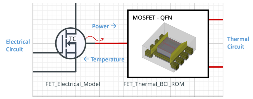
So what’s possible? A thermal BCI-ROM in VHDL-AMS format can directly connect to electrical circuit elements. The thermal circuit shown below will communicate temperature to the electrical circuit element, and the electrical circuit will send power back. This is not actually a ‘back and forth’ co-simulation approach. Thermal and electrical circuits are solved concurrently as they are described in the same language.
Model supply chain and connecting BCI-ROMs
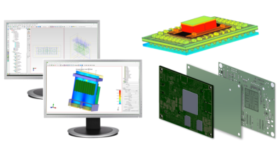
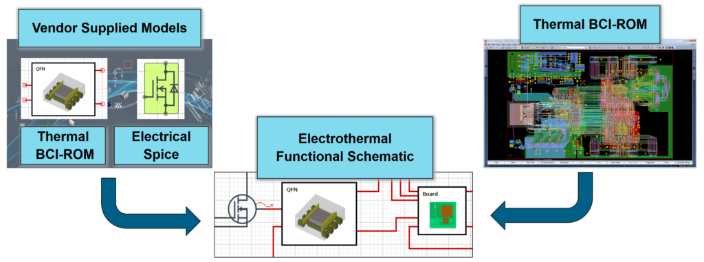
The model supply chain is well established for electrical design. It’s common today to request and receive behavioral models of devices (in spice or VHDL-AMS formats) as part of the functional electrical design process. These electrical models are portable, i.e., they will interact properly with any other component in the functional schematic and can be consumed by many simulation tools. The same is now true for thermal models, thanks to the boundary condition independent nature of these thermal BCI-ROMs and their implementation in VHDL-AMS, an IEEE standard format. Any simulation tool that supports VHDL-AMS can leverage this type of BCI-ROM to predict accurate response in any thermal situation environment modeled.
A semiconductor vendor for example, can now support their customers by supplying both electrical spice files and thermal BCI-ROMs. The customer can create a thermal BCI-ROM of the PCB, connect them together with other thermal BCI-ROMs and electrical models to quickly assemble a functional schematic representation of their product that captures all electrothermal behavior.
The availability of an accurate electrothermal functional schematic early in the design process brings together thermal and electrical design to enable concurrent design at the system level. The electrical design engineer benefits from an understanding from the beginning of how the electrical functionality and performance of the product will be impacted by temperature and temperature differences. The thermal designer benefits by gaining access to accurate power dissipation values far earlier in the design process, early visibility on what components are likely to need remedial thermal action, and the ability to design power control strategies from the onset.
Smartphone Power Control, Thermal Throttling – Digital Electronics Example
Let’s look at an example how this works with Simcenter Flotherm, electronics cooling software, by generating BCI-ROMs from 3D thermal models and then using them in PartQuest Explore, circuit simulation software. You can try out the electrothermal circuit simulation example in a link below, but first I will take you on a tour of what is included.
The example model is an electrothermal design of a generic Smartphone, with a power throttling algorithm defined. This is the same application that my colleague Mike Donnelly wrote about in the past to explain thermal netlists, but this time the thermal circuit is built with connected thermal BCI-ROMs instead of a single thermal netlist.
Processor 3D thermal model and generating a BCI-ROM
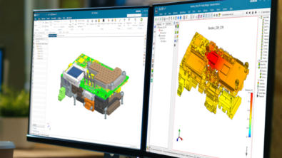
Let’s focus first on the processor. In Simcenter Flotherm, the processor model looks like this:
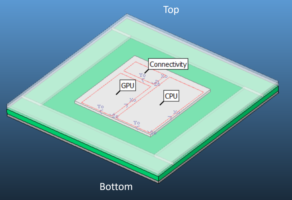
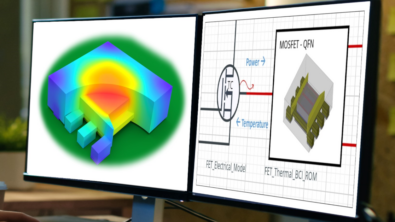
There are three named heat source zones on the die: CPU, GPU, and Connectivity. There are two defined boundaries from which heat can exit the model: Top and Bottom. When this Simcenter Flotherm model is converted into a FANTASTIC thermal BCI-ROM and imported into PartQuest Explore Cloud it looks like this:
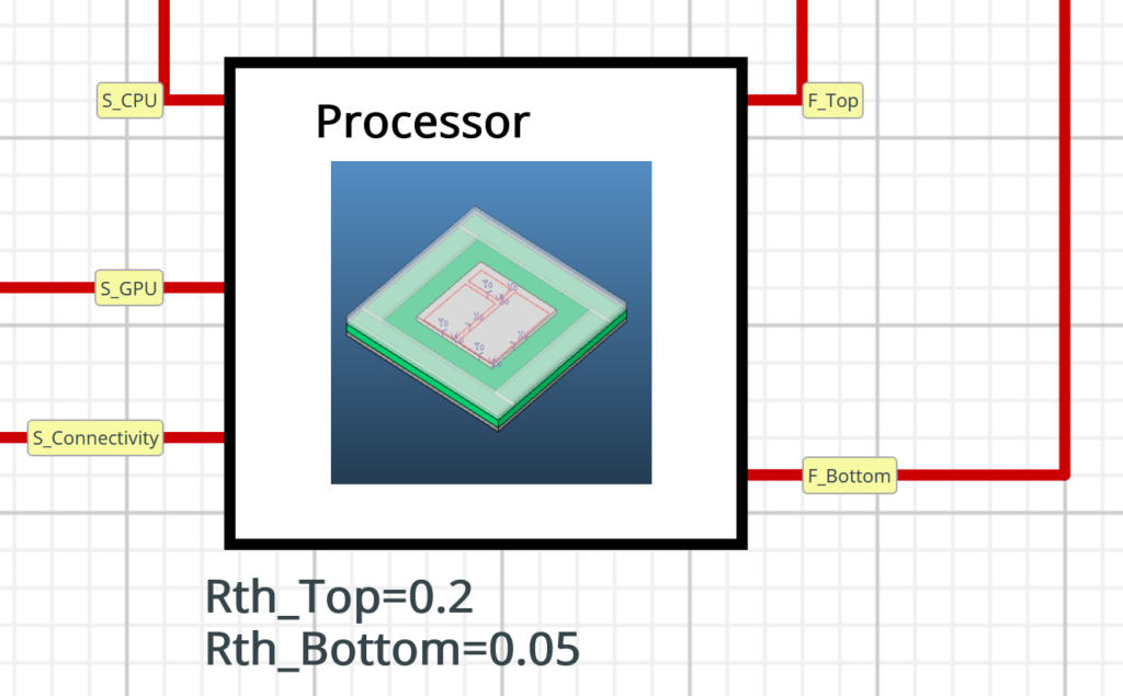
Each heat source has a thermal connection to carry power and temperature information, as does each defined boundary face. Note that each boundary face requires a thermal resistance (Rth) to be specified. More information below.
Incorporating multiple thermal BCI-ROMs into the electrical circuit simulation model
The BCI-ROM is then connected to the electrical circuit, establishing the power-temperature connection, and also connected to the rest of the thermal circuit. Each connection for a thermal boundary face requires a user input for thermal resistance between the BCI-ROM and the next thermal object in the circuit. This is how the Boundary Conditions for the BCI-ROM come into play. In this example, the Bottom face of the processor is connected directly to the appropriate location on the PCB BCI-ROM with Rth_Bottom = 0.05 K/W (assuming a small thermal resistance between the bottom of a component and the board is usually reasonable). The top of the processor also has a boundary face Rth. This generally could represent a connection to a heat sink, airflow, etc, but in this case it represents a direct connection to the phone casing via a thermal interface material (Rth_Top = 0.2 K/W) between the processor lid and the casing.
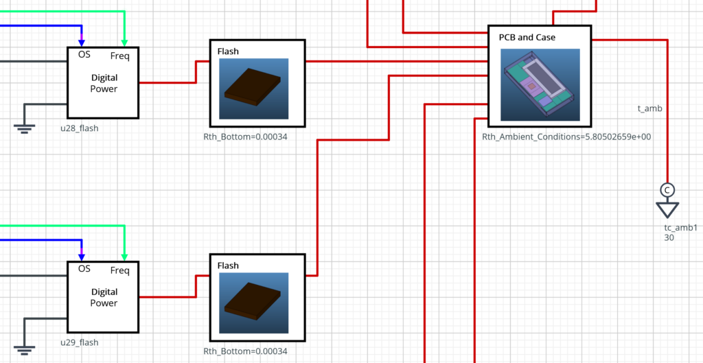
In addition to the processor, two memory chips are included as thermal BCI-ROMs, and finally the ‘rest’ of the Smartphone (containing the PCB, battery, display, temperature sensor, and phone casing) is included as another BCI-ROM. Note that the thermal BCI-ROM boundary faces for the components are connected directly to corresponding PCB BCI-ROM heat sources. This specifies that heat exiting the components will enter the ‘PCB and Case’ BCI-ROM at the correct physical location, and then accurately move within that BCI-ROM before arriving at the ambient reference temperature.
The electrical side of the circuit contains three items of note:
- ‘Digital Power’ VHDL-AMS. The digital power model is an abstract representation of the power dissipation behavior of any clocked digital IC. The instantaneous power dissipation is a function of the applied voltage, the clock frequency, the operating state, and the temperature. The user can specify the nominal values for these parameters, and the model dynamically adjusts the power dissipation as they change during transient simulation.
- Operating State Definition. For this example, the system is Idle for 100 seconds, then in Gaming Mode for 1500 seconds.
- Dynamic Thermal Management (DTM) Controller. The sampled-data algorithm is attempting to keep the sensor temperature (on the phone casing, just above the processor) between 40 °C and 45 °C. It does this by adjusting the global clock rate in a simple manner:
- Sensor Temperature is too hot? Halve the clock frequency
- Sensor Temperature is too cold? Double the clock frequency
Transient electrothermal circuit simulation power – aware control
Transient thermal analysis is and will continue to be more crucial in the future of thermal design.
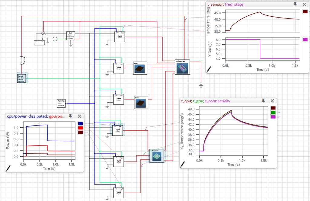
In this simulation the DTM controller responds as shown below. The increased power dissipation from ‘gaming mode’ at the maximum clock frequency causes the sensor temperature to exceed 45 °C at ~750 seconds activating thermal throttling control response. the DTM controller halves the frequency in response, dropping the power dissipation and the sensor temperature, and of course dropping the performance of the gaming software at the same time.
Explore using BCI-ROMs, generated by Simcenter Flotherm, in PartQuest Explore
The PartQuest Explore online simulation model is linked to below. There are a few parameters (look for the blue boxes) that are available to change directly.
- Note – Things to Try:
- Determine the impact on device performance of eliminating the heat path from the top of the processor to the phone casing by setting Rth_Top = 50 K/W
- Comment: this causes the Processor temperatures to be much higher obviously, but it also introduces a slower thermal response to processor power changes. In this situation, the DTM controller halves the clock frequency 3 times before the sensor temperature drops below 45 °C, creating a very uneven gaming experience for the user.
- Determine the impact of changing the nominal power dissipation for the CPU to 2W.
- Try different values for the DTM policy, max and min temperatures, sampling period
- Determine the impact on device performance of eliminating the heat path from the top of the processor to the phone casing by setting Rth_Top = 50 K/W
Launch PartQuest Explore example in your browser: https://explore.partquest.com/live-embed-design/388554
Also note, to access the full interactive design, click the ‘Edit in PartQuest Explore’ button, make a copy of the design and explore!
Learn how ROHM uses Simcenter Flotherm BCI-ROM technology
View this on-demand recorded presentation:
Accelerate electronic systems design with thermally aware electrical simulation
Discover insights from Ippei Yasutake, Group Assistant Manager of Solutions Engineering at ROHM Co. Ltd, on the advantages of BCI-ROM technology to enable Rohm customers to reduce costly re-spins and increase productivity through fast, accurate electro-thermal circuit simulation of their designs.
Your questions answered on using BCI-ROMs in a circuit simulation
If you are a circuit simulation user, please see the 2023 Linkedin Live event recording: Beat the heat: New technology to solve electronic design thermal challenges
and the related blog that answers several questions raised during that event: Eight questions on BCI-ROM answered
The future of thermal design: BCI-ROM technology for multiple simulation purposes
View Simcenter Flotherm BCI-ROM factsheet – download
This details the current formats supporting matrices format (standalone solution) , FMU format for system simulation tools, VHDL-AMS format for circuit simulation tool use, and finally Embeddable BCI-ROMs (reduced order 3D accurate thermal models of IC packages for 3D CFD simulation). Please note that Simcenter Flotherm XT software also has this BCI-ROM generation capability and so does Simcenter FLOEFD software (leveraging the BCI-ROM and Package Creator Module). (Note: only Simcenter Flotherm supports Embeddable BCI-ROM creation however at this time.)
Supporting 1D fluid flow network analysis with Boundary condition independent reduced order models (BCI-ROMs in FMU format)
Video: How to use Simcenter Flotherm Reduced Order Models (BCI-ROM) in Simcenter Flomaster – a liquid cooling example
Thermal Netlists compared to BCI-ROMs
Thermal netlists are reduced order model data that is valid for a set range of boundary conditions.
Blog: Electrothermal circuit simulation enabled by VHDL-AMS thermal netlists
Video: [TECH TIP] Thermal netlist export in .sp format workflow for users
References:
- L Codecasa, V d’Alessandro, A Magnani, N Rinaldi, PJ Zampardi, “Fast novel thermal analysis simulation tool for integrated circuits (FANTASTIC)”, 20th International Workshop on Thermal Investigations of ICs and Systems (THERMINIC) article 6972507 United Kingdom, 2014.