Frontloading electrical circuit analysis with thermal models
Remember ENIAC, the first all-electronic computing system that weighed 30 tons and occupied over 90 m2? Thankfully, the progress of electronics design has not stopped and now a typical smartphone can perform billions of operations per second. A combination of high-performance electronic components and a reduced PCB size led to an increase in signal-processing operating speed. Miniaturizing electronics, in turn, raised power density and heat dissipation from electronic devices.
Combining thermal and electrical models
Designing electrical and thermal systems separately may lead to various problems such as late design changes due to poor thermal management. Delays at the design stages of a product are unacceptable in the current environment, hence both electrical and thermal systems should be designed as one. To avoid these inefficiencies, Simcenter FLOEFD team had previously announced a Thermal Netlist VHDL Export feature. This was the first step towards a true electrothermal design which came with a limitation, only a single thermal environment (i.e. peripheral heat transfer coefficients) could be simulated with the extracted model.
To eliminate this limitation, previously introduced Boundary Condition Independent Reduced Order Models (BCI-ROMs) can now be exported in the IEEE Standard 1076.1 VHDL-AMS format from a recent release of Simcenter FLOEFD 2021.1. These extracted models, being boundary condition independent, allow changes to their thermal environment while maintaining the requested level of accuracy. Multiple transient heat sources are still fully supported.
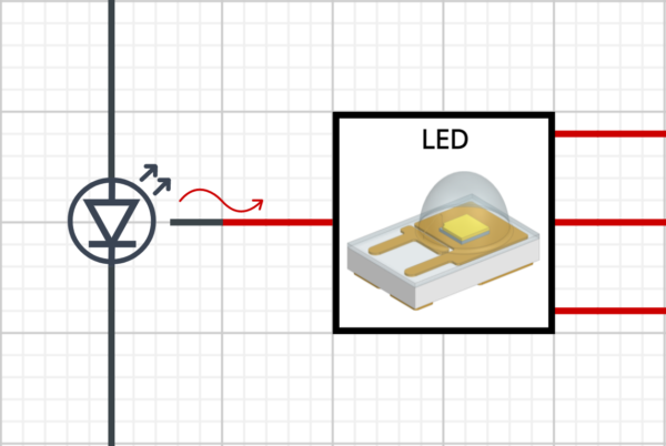
As can be seen from the image above, an electrical and a thermal BCI-ROM model can now be connected together and used in a single system. During a simulation, an electrical component will generate heat which will be used in the thermal model to calculate the component’s temperature. Since electrical and thermal models are written in the same language, they will be solved at the same time.
VHDL-AMS models supply chain
Creating thermal BCI-ROMs in VHDL-AMS format makes them portable and easy to use in any electronics simulation environment, which supports VHDL-AMS. While supplying an electrical model of a component or a device is common practice among electronics manufacturers, the same is not true for thermal models. However, this is about to change. Now a camera (or any device) manufacturer, having thermal BCI-ROM and electrical models, can request similar models from a chip manufacturer in order to connect them to their circuit. It is a win-win situation for both electrical and thermal engineering teams, as the performance of a device can be analyzed in different thermal conditions and power control strategies can be designed accordingly.
ADAS Camera Example
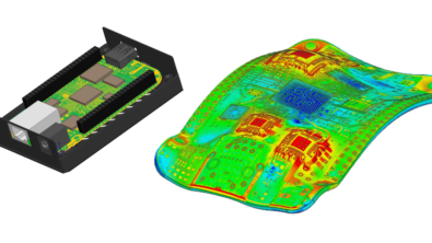
Everything is easier to understand if there is an example, therefore, let’s see how a thermal BCI-ROM exported from Simcenter FLOEFD, CAD-embedded multiphysics solution, can be connected to an electrical circuit in PartQuest Explore, circuit simulation cloud software.
An electrothermal circuit of a generic ADAS camera was designed, which incorporates a few power profiles to account for simple driver assistance features and long-awaited full self-driving mode. The model also accounts for thermal throttling.
3D thermal model and BCI-ROM of an SoC
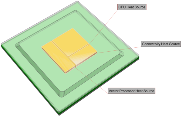
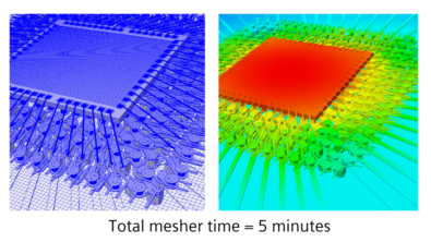
Having mentioned chip manufacturers, first, let’s see how a thermal BCI-ROM can be exported from Simcenter FLOEFD. Below is an image of the imported thermal BCI-ROM of a general System on Chip (SoC) used in an ADAS camera. Thermal connections (i.e. red nets) are capable of carrying power and temperature information, however, a thermal resistance (Rth) must be specified for each boundary face.
The die of the main SoC has three heat source zones: CPU, Vector Processor (VP) and Connectivity. To transfer the generated heat from the SoC to the PCB and the heatsink, two boundary conditions were defined.

Integrating thermal BCI-ROMs into an electrical circuit analysis model
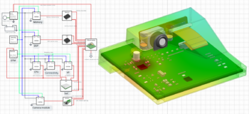
Thermal BCI-ROMs can be used individually (i.e. connected straight to an electrical circuit via a thermal port) or to create a thermal circuit. When connecting thermal models together, you are required to specify a thermal resistance between the BCI-ROM and the next thermal object in the system. In this example, the SOC, a DSP and a memory chip were exported from Simcenter FLOEFD as thermal BCI-ROMs and then connected to the PCB and the casing of the camera, which acts as a heatsink. A small thermal resistance between the PCB and the SoC was assumed, which is specified in the model. A higher value could be specified for a thermal connection to the heatsink to simulate the effect of a thermal interface material. Thermal boundary faces of the SoC are connected to the corresponding PCB BCI-ROM heat sources. Effectively, this allows the transfer of heat from the component to the correct physical location on the PCB. The heat will be dissipated once it reaches thermal ambient reference after traveling through the PCB BCI-ROM.
While the aforementioned components have their own thermal BCI-ROMs, a step-down regulator was included in the “PCB and casing” BCI-ROM. Although it was not exported as a separate component, it still has a thermal connection, as it was modeled as a thermal heat source in the 3D model. The diagram below shows an example of a thermal network. Notice how thermal BCI-ROMs of components are connected to the thermal BCI-ROM of the PCB via thermal nets going from boundary faces to heat sources.
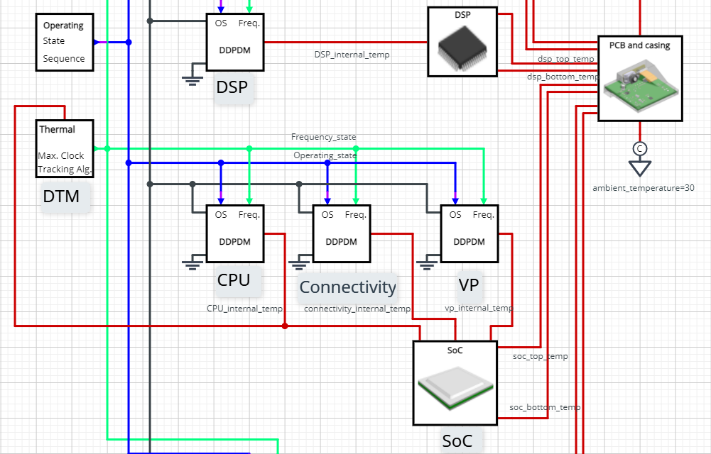
Here is a list of components that make up the electrical circuit:
- Digital Device Power Dissipation Model or DDPDM. This model allows you to represent power dissipation of any clocked digital integrated circuit. Temperature of the IC, the applied voltage, the clock frequency and the operating state are used as inputs to calculate power dissipation.
- Operating State Sequence. This item allows you to define power values for different scenarios. There are three states in this example: idle, driver assist and full autonomy. The user can easily change the duration of states and their order.
- Dynamic Thermal Management (DTM) Controller. This is a simple clock rate controller, which reduces (halves) the clock frequency of the SoC, if its temperature exceeds 60 degC, and increases (doubles) the clock frequency if temperature is below 50 degC.
- Battery. Used to power the electrical components.
- Buck converter. Brings the voltage down to the specified value.
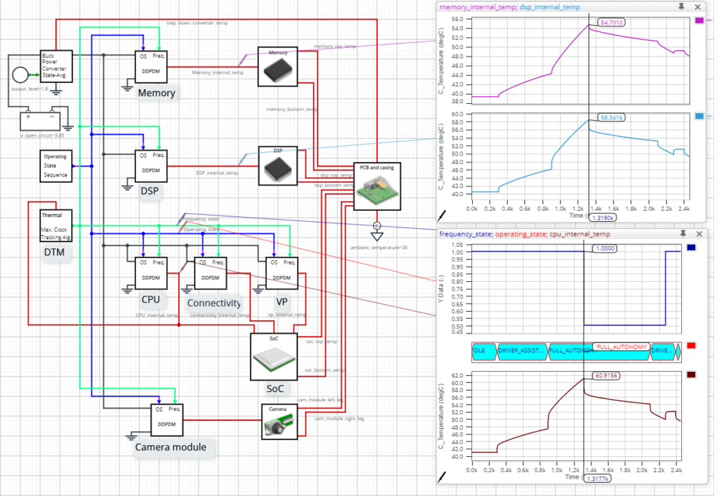
Preventing overheating – Dynamic Thermal Management
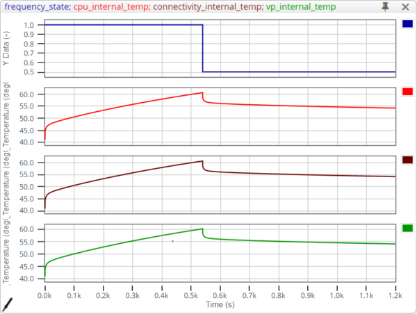
The plots below represent how implemented thermal strategy affects the performance of the ADAS camera. During the most intensive use case, that is when the “full autonomy” operating state is active, the temperature of the SoC exceeds the threshold value due to increased power dissipation leading to thermal throttling. To prevent overheating, the DTM controller reduces the clock frequency by 50%, which decreases power dissipation and temperature of the SoC. Unfortunately, the performance of the camera unit would also be hurt in this scenario, compromising safety.
Explore capabilities of BCI-ROMs yourself
Here is a link to the PartQuest Explore model shown in this post: https://explore.partquest.com/node/465264
Change any parameter by double-clicking on a component and run the model with your settings or click “Edit in PartQuest Explore” button to create a copy for yourself! Try to:
- Determine the impact of changing the ambient temperature to 20 degC.
- Create a different strategy for the DTM controller.
- Decrease thermal resistance between the casing of the camera and the outside world. Could a different heatsink design prevent overheating?
Additional resources on reduced order modelling
If you would like to see more reasons why BCI-ROM technology is worthwhile, below is a video showing why BCI-ROMs should be used and how to export them Simcenter FLOEFD: