Simcenter FLOEFD 2020.2: What’s New?
The latest release of CAD-embedded Simcenter™ FLOEFD™ 2020.2 is here! Simcenter FLOEFD is a CAD-embedded computational fluid dynamics (CFD) solution. Due to its unique technology, it can reduce the overall simulation time by up to 75%. This new release provides a range of new features and enhancements including free surface simulations for rotating geometry, and export of thermal and pressure loads for Solid Edge Simulation. Let’s take a look at the list of new functionalities available in the latest release:
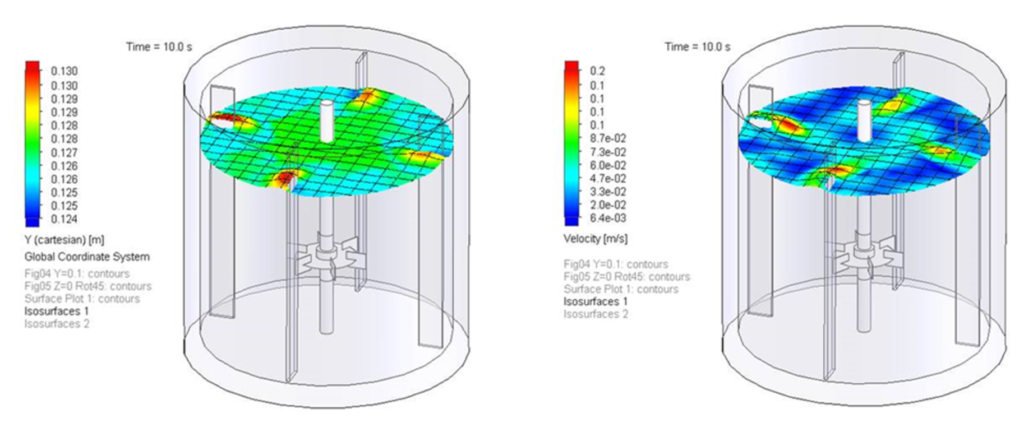
Free Surface with Rotation
With the new free surface (Volume of Fluids – VOF) extension you can now consider rotating geometry and free surface. This capability lets you model partially submerged pumps that work with a liquid and air mixture of fluids or simulate the liquid surface in a mixing tank that has a mixing propeller in it – inside your CAD software.
Simcenter FLOEFD for Solid Edge to Solid Edge Simulation Interface
Export Simcenter FLOEFD results for temperature and pressure loads for use in structural simulations of Solid Edge Simulation. With the “Export Results to Simulation” command, the relevant surfaces can be exported into Solid Edge Simulation. Depending on the structural simulation type, choose if thermal and/or pressure loads should be imported and select the corresponding Simcenter FLOEFD result file (*.fld file) in Solid Edge Simulation (starting with Solid Edge 2021).
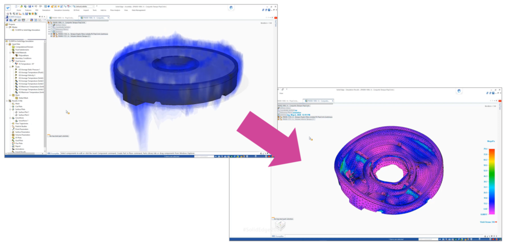
This functionality helps Solid Edge users leverage pressure and temperature loads from Simcenter FLOEFD in their structural simulations for more accurate results.
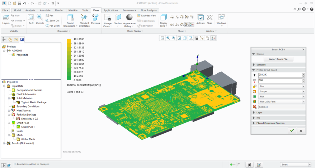
SmartPCB Material Selection
The SmartPCB model has been further improved. Now you can select custom materials for the conductor and dielectric materials. Previously only copper and FR4 were applied but nowadays a wider range of materials can be used including ceramics and aluminum.
The SmartPCB model can now allow for initial temperature definition in the SmartPCB menu. It also enables thermal conduction out of the previously insulated PCB thin side walls . This allows for a broader application of the SmartPCB and higher accuracy.
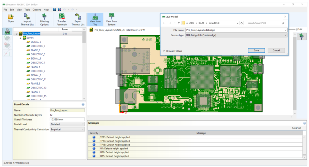
Save Changes in Simcenter FLOEFD EDA Bridge
Save any settings from Simcenter FLOEFD EDA Bridge for the PCB that you plan to import into Simcenter FLOEFD and continue from where you left off or re-use it at a later stage. This functionality makes it easier to return to the import settings or repeat PCB imports with the applied changes to the PCB design (size or component positioning). These changes are saved in the *.edabridge file.
BCI-ROM Export as FMU
Export Functional Mock-up Unit (FMU) models with the help of the recently introduced Boundary Condition Independent Reduced Order Model (BCI-ROM). Use FMU models in Simcenter Amesim, Simcenter Flomaster, Simcenter STAR-CCM+ as well as Simcenter FLOEFD and other FMU supporting 1D and 3D CFD tools. This gives a wider application of BCI-ROMs besides the previously supported MATLAB® and GNU Octave and allows for 1D and 3D tools to import and use BCI-ROM models in co-simulations.
BCI-ROM Console Solver
Solve BCI-ROM models without the need for any other tools such as MATLAB® or GNU Octave. However, this functionality will not provide the complexity and connectivity to other parts of a larger system simulation setup which can be done in those tools. The solver can be started with the Simcenter FLOEFD executable routine (Results_Exporter.exe). More information can be found in the Simcenter FLOEFD Online Help.
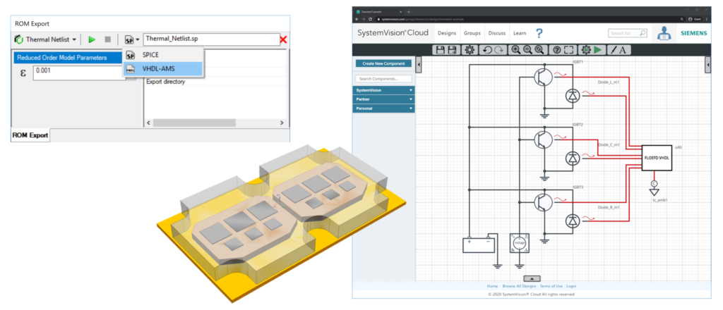
Thermal Netlist VHDL Export
Export Thermal Netlist models to Very High Speed Integrated Circuit Hardware Description Language (VHSIC-HDL, in short VHDL) format which can be read by Mentor’s Xpedition-AMS, System Vision Cloud and other VHDL supporting tools. This makes the Thermal Netlist more versatile and usable by other tools as well, besides Spice simulators.
CATIA-to-NX CAD-Model & Simcenter FLOEFD Project Converter
Convert complete CATIA V5 models with Simcenter FLOEFD projects into Siemens NX models with Simcenter FLOEFD projects with this functionality. The data converted includes CAD model as well as the Simcenter FLOEFD project definition and maintains all geometry references. This feature saves project set-up time and assists organizations who need to transition from CATIA V5 to Siemens NX. A batch conversion of files is also possible. Please look for detailed information in the Simcenter FLOEFD Online Help.
Import Solid Edge Materials
Simcenter FLOEFD imports materials defined on the components of an assembly in Solid Edge for simulation in Simcenter FLOEFD projects. This makes the setup of simulation projects more efficient and avoids repeating steps or even manual material creation.
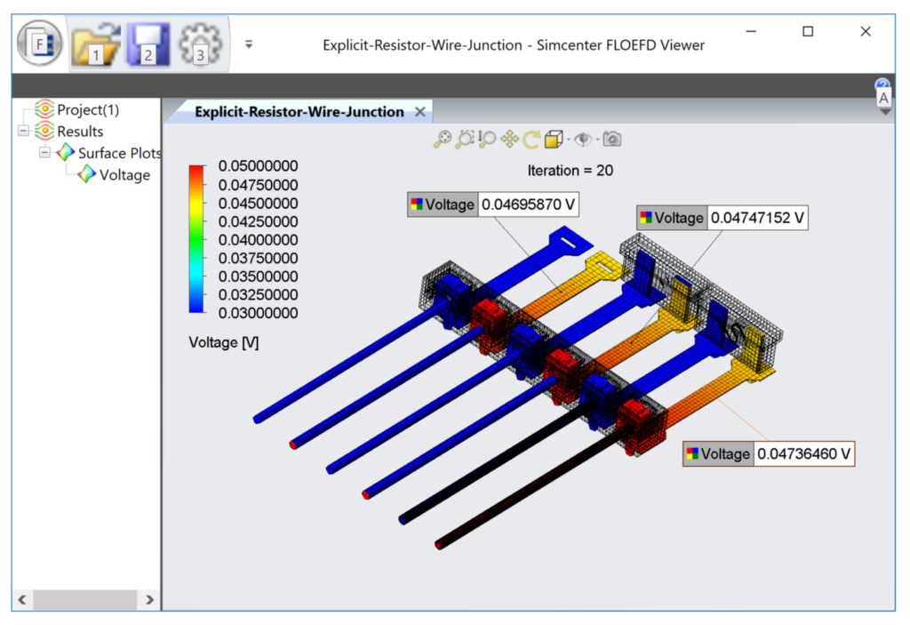
Dynamic Probe in Simcenter FLOEFD Viewer
The Simcenter FLOEFD Viewer now shows probes created originally in Simcenter FLOEFD. This enables you to point out specific points and their exact value in the plots rather than trying to read it off the color bar.
Simcenter FLOEFD EDA Bridge File Storage for Simcenter FLOEFD for CATIA
Often component names such as IC1 will cause CATIA to complain about existing files when importing multiple PCBs. As such, Simcenter FLOEFD for CATIA will create a separate folder for imported EDA files through Simcenter FLOEFD EDA Bridge. This enables in large assemblies the import of multiple PCBs without errors related to existing files with the same name.
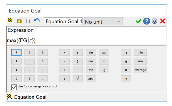
Calculating Min, Average and Max Values with Equation Goals
The new functions in equation goals allow you to define Minimum, Average and Maximum from the set of Goals or parameters. Regular expressions are supported to handle a huge number of parameters. For example, the expression Max({VG BatteryName .*}) will give you the maximum from all goals starting with “VG BatteryName”. This makes the evaluation of many similar goals for their highest, average or lowest value very efficient.
Goal Plot until the Loaded Physical Time Moment
Instead of to the end of physical time, this functionality now creates a goal plot only up to the time moment that is loaded.
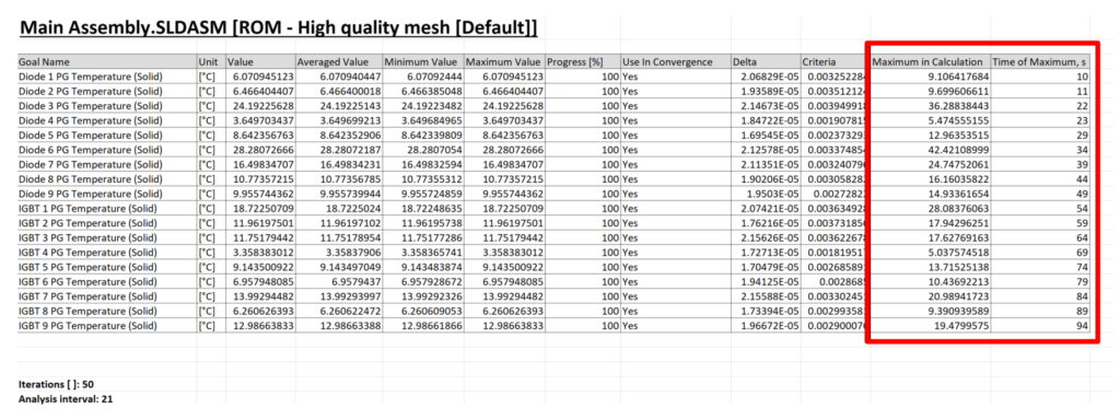
Display Maximum Goal Value from Transient Calculation including Time Moment
The goal table now lists the maximum goal value of a transient simulation with its corresponding time information. This function enables you to easily evaluate both the value and the exact time when the maximum value of a goal occurred.
Point Goals can be set in the Center of a Component
This new option enables you to define a point goal at the center of a component by selecting the component from the model tree. For example, now you can find out the temperature at the core of a component easily. In addition, you can disable the interpolation so that the point goal shows the value of the mesh cell. This feature is especially important for BCI-ROM models where only point goals can be used and results are typically of interest at the core of the component.
Feature Goal is available before Creating the Feature
Use feature goals in the dependency definitions of the boundary condition itself, before the boundary condition is defined. Previously such feature goals were created only after boundary condition creation. Therefore they could not be used during creation. This new functionality makes the definition of a boundary condition with dependency more efficient.
Point Parameter Coordinates Through Import from CSV or Text-Files
Define point parameters with exact coordinates for their location. When defining a larger number of such point parameters, it can be quite time-consuming to manually enter all the coordinates. Now this process can be automated by importing the coordinates from a CSV or Text file. Thereby, speeding up the process, especially for a large cloud of point coordinates.
Create Heat Sources separately for each selected Component/Surface
You can now create heat sources in the same manner as goals for individual surfaces or components when making multiple selections. This makes applying the same heat source to multiple surfaces/components, as individual boundary conditions, much easier and faster.
New ‘mil’ Unit
A new length unit has been added – “mil” is one thousandth (1/1000) of an Inch.
Electrical Resistance: Total Value
In addition to material thickness and selection of predefined resistances from the Engineering Database, you can now set a value of total electrical resistance. This makes it easier to perform design explorations varying the value in the Parametric Study.
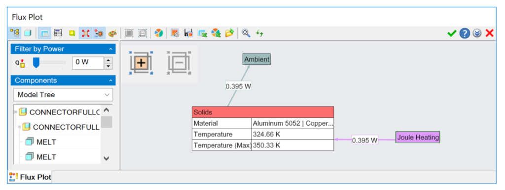
Flux Plot Energy Balance for the Whole Task
You can now group all displayed nodes by their types. When displaying the graph for all components and then grouping all, it will give you an overall energy balance. In addition, radiation is split into Directional, Thermal and Solar radiation amounts. This makes the evaluation of large assemblies easier and provides a more detailed as well as overall view on the results.
New CAD System Support
Solid Edge 2021 is now supported.
The Simcenter FLOEFD Standalone version is using now an updated CAD kernel.
If you have missed the news on version 2020.1, you can find more here.
For additional information on the latest release of Simcenter FLOEFD CFD simulation software, please go to the Support Center site or read the release highlights in the installation package.
What to read next:


Comments
Comments are closed.
Dear Boris,
Great news, thanks!.
Best regards,
Blas.