What’s new in Simcenter Flotherm and Simcenter Flotherm XT 2210 software releases!
Discover what’s new in the Simcenter Flotherm and Simcenter Flotherm XT electronics cooling software 2210 releases. These new October 2022 releases continue to build on 34+ years of development and regular user feedback. Read on to explore new features that help thermal engineers, designers, and analysts to go faster, model the complexity in electronics thermal management and stay integrated with related engineering disciplines during electronics development.
Simcenter Flotherm 2210 – What’s New

Stay Integrated
Thermo-mechanical analysis workflow – electronics cooling simulation to FEA analysis
Increasing power densities require careful thermal performance and reliability consideration. For example, the rise of 2.5 and 3D semiconductor advanced package designs has resulted in increasingly complex thermal interaction between adjacent areas of the package, so it is critical to consider thermo-mechanical failure mechanisms.
Thermo-mechanical effects must be evaluated to de-risk semiconductor IC package design, improve PCB thermal reliability and reduce system level product failures. The ability to use accurate temperature results from electronics cooling simulation tools to perform FEA analysis for mechanical stress, creep, fatigue and durability studies is increasingly crucial.
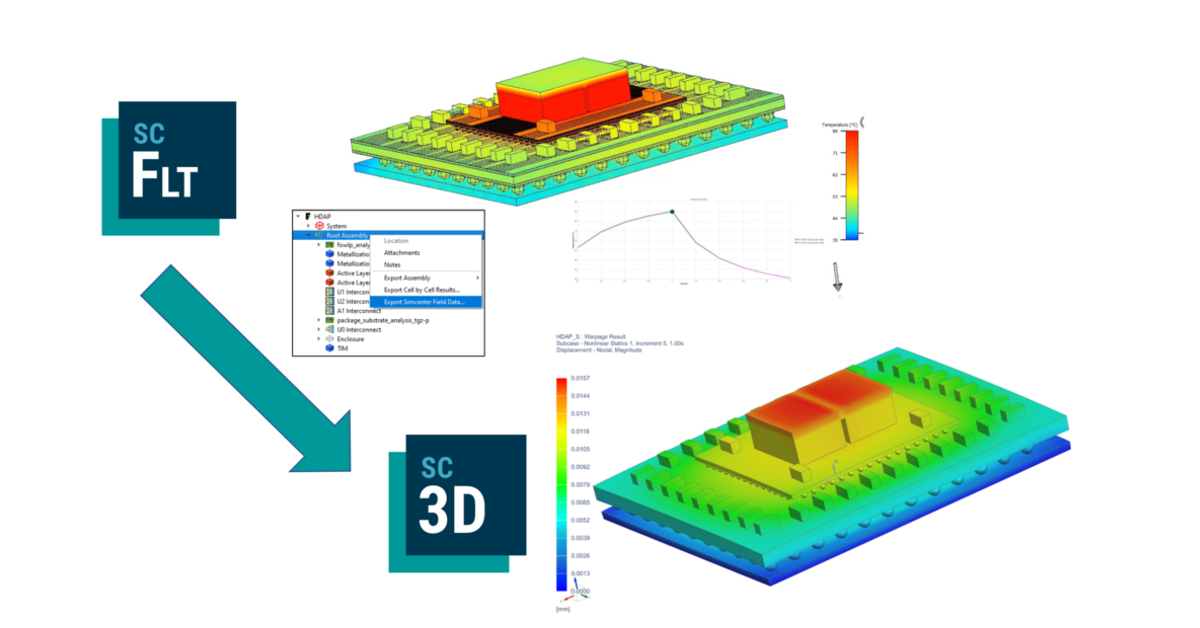
Using Simcenter tools, engineering teams can shorten this workflow. In Simcenter Flotherm 2210, you can now export solid temperature results for the entire model, or a nominated assembly quickly. With one click access, a Simcenter 3D standard file format (.FLD) is generated. Both steady state and transient temperature field data can be exported. For transient data, the entire event can be exported or smaller time period selections can be specified. This export process is also fully supported with scripting for any automation purposes
How to export 3D temperature fields from Simcenter Flotherm to Simcenter 3D
Go Faster
Visualization enhancements reduce thermal model creation time
Electronics thermal models often have 1000’s of components. Model navigation, geometry selection and manipulation for large complex models is now far faster and easier with an additional visualization window separate from the project manager window.
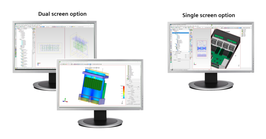
This means as a user, you can open a Visualization Viewer separately and place alongside drawing board or existing analysis window, or it can be opened on a separate monitor. Object selection is synchronized across all windows and implemented changes show immediately.
How to use the new separate visualization window in Simcenter Flotherm
In the above video demonstration, the following is shown:
- separate viewing and project manager windows and controls
- solid & wireframe views and orientation viewing
- making selections and changes
- duplication of results plots between Visualization Viewer and Analysis Mode
The demonstration also briefly reviews several prior visualization and post processing related enhancements over recent years in Simcenter Flotherm that help productivity, such as:
- faster generation of tabular results for grouped selections of components
- faster results plots e.g surface temperature plots
- Automatic maximum temperature annotation and automatic movement of temperature cut plane plots to max temperature location for a series of studies
- Post processing automation with Floscript

Model the complexity
Accurate transient thermal analysis at microsecond timescales
Engineers can now accurately represent sub-microsecond time variations for thermal analysis of power cycling of IC packages, many power semiconductors and other devices and systems in Simcenter Flotherm.
This uses double precision technology to enable accurate solving for transients of any timescale so you can:
- Define time varying conditions in microseconds and lower.
- Set time steps to the order of microseconds and smaller.
- Evaluate complex power variation influences and successive rapid transients with higher fidelity
IC thermal design: model overlapping powered areas using the Die SmartPart
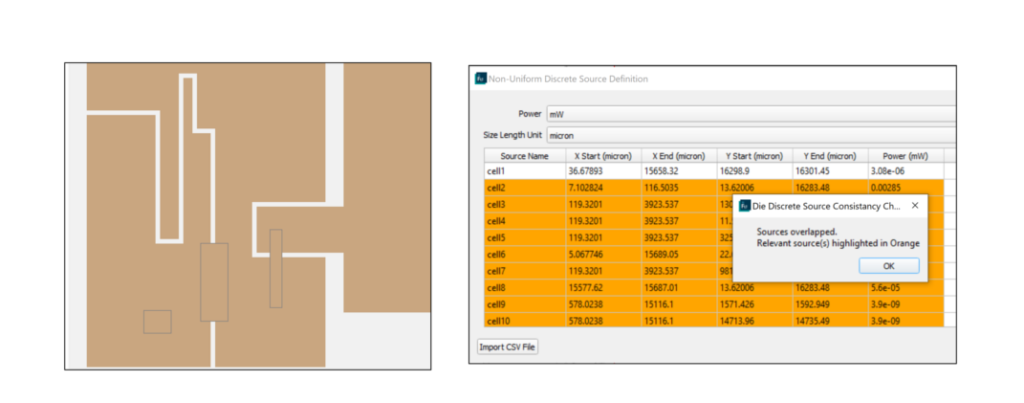
Detailed power maps extracted from silicon layouts in IC design workflows often have overlapping power blocks. These can be time consuming to account for and configure in thermal models to accurately represent them.
Simcenter Flotherm users can now leverage overlapped power zones, defined in a CSV file and imported into the Die SmartPart. This speeds up creation of accurate complex die structures by allowing greater flexibility. When discrete sources are defined for a non-uniform die dissipation in the Die SmartPart the following occurs:
- Powers are additive in the overlapped zone
- A message displayed when overlaps are detected confirms intent
Simcenter Flotherm XT 2210 – What’s new in CAD centric electronics cooling CFD
Go Faster
Faster PCB electro-thermal modeling with enhanced controls
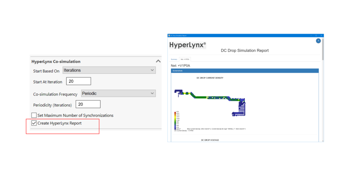
There is a high accuracy setting for HyperLynx PI co-simulation. This co-simulation capability was originally released in Simcenter Flotherm XT 2020.2. Introduced now at the 2210 release are enhanced controls for co-simulation settings for how often power and thermal simulations are synchronized which offers reduced overall simulation time. This is suitable as it is not necessary for accuracy to synchronize temperatures and powers after every iteration in most applications.
Users now have control over number of DC drop calculations as options:
- delay start of calculation to part way through thermal simulation.
- perform at every iteration or periodically.
- define maximum number of DC drop synchronizations.
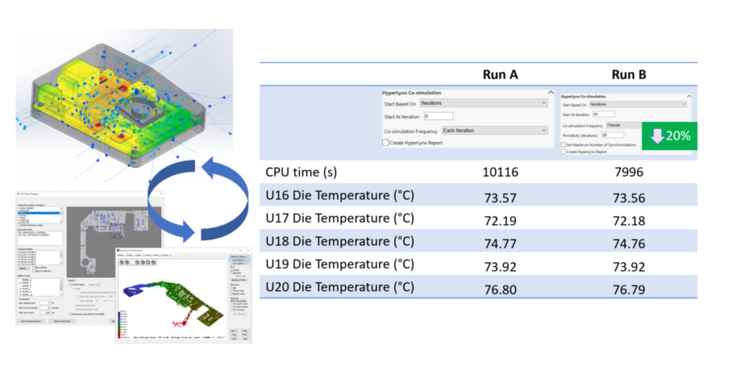
Additionally, you can now generate a HyperLynx PI report to provide DC Drop simulation data as part of the co-simulation driven by Simcenter Flotherm XT.
How to perform PCB electro-thermal co-simulation using Simcenter Flotherm XT and HyperLynx PI
You can take a look at this demonstration video on the co-simulation set up and execution at version 2020.2 and see where the new 2210 release features above now further enhance this workflow.
Model the complexity
How to incorporate a PCB solder mask for improved model fidelity
As part of the commitment to modeling PCBs at all levels and stages, from simple initial concepts to detailed design stage representations of fully routed board, there is a new enhancement that allows users to better model correct physical dimensions of boards by including solder mask information.

Using EDA Bridge, users can now incorporate PCB solder mask layers during PCB import. You can:
- Control level of detail when transferring to main project
- Choose options for importing whole board, or with separate settings for individual thermal territories.
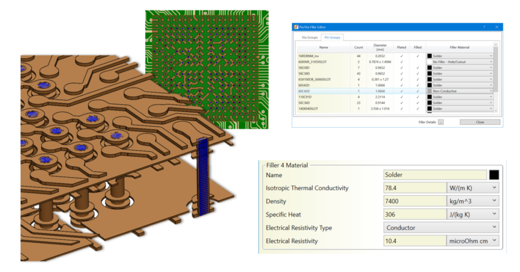
Faster definition of Pin or Via material properties on a padstack or group basis
Modern PCB designs may have a high number of Pins and Vias. If not using simply a default setting for all via and pin material properties, the assigning of different material properties to individual or groupings of hundreds of different via or pin geometry is a detailed time-consuming task during a model set up.
In Simcenter Flotherm XT’s EDA Bridge, a new Pin/Via Filler Editor has been introduced for editing material properties in groupings prior to transfer. This way upon transfer of explicit nets and/or territories the geometry of the via and filler is automatically created and the correct material properties applied. This eliminates considerable pre-processing steps while improving accuracy so you can focus more on the of PCB thermal analysis results.