Eight questions on BCI-ROM answered: solve thermal design challenges earlier in circuit simulation
We recently hosted a LinkedIn Live session: “Beat the heat: New technology to solve electronic design thermal challenges,” that focused on new BCI-ROM models that can be used in circuit simulation for accurate electro-thermal modeling of components.
We had some great questions during the live session, so we have summarized them with answers below to share! Please comment if you have any additional questions for the presenters.
Quick review: BCI-ROMs for circuit simulation
BCI-ROM stands for Boundary Condition Independent Reduced Order Model. This technology is a modeling approach to capture thermal characteristics from a 3D analysis, in an accurate fast-solving reduced order model that can be used in any thermal environment. These are particularly useful for transient analysis.
For circuit simulation electro-thermal simulation, BCI-ROM models are created in IEEE Standard VHDL-AMS format. They leverage the language’s capability to express the simultaneous differential equations needed to represent the dynamic thermal characteristics. These equations are expressed in compact matrix-math form.
1. Is it easy to import and use BCI-ROMs in a circuit simulation model?
As shown in the demonstration at the event, it is straight forward to use a component that is configured as a BCI-ROM in PartQuest Explore. A BCI-ROM library model can be linked to power sources and boundaries, e.g to define an ambient temperature or connecting to other BCI-ROMs. You specify powers and can designate probes to report plots of transient temperature results that the BCI-ROM has been specified to output when a simulation is run.
For semiconductor OEMs, creating BCI-ROMs for their PartQuest Explore component libraries, the process of data import is easy and familiar. The input files from Simcenter Flotherm for the BCI-ROM includes a .vhd file that you copy the script from and paste into the PartQuest Explore component editor window. You then edit the icon appearance and locations around the icon for connections of power and boundaries. The BCI-ROM matrix information is imported as a .csv file.
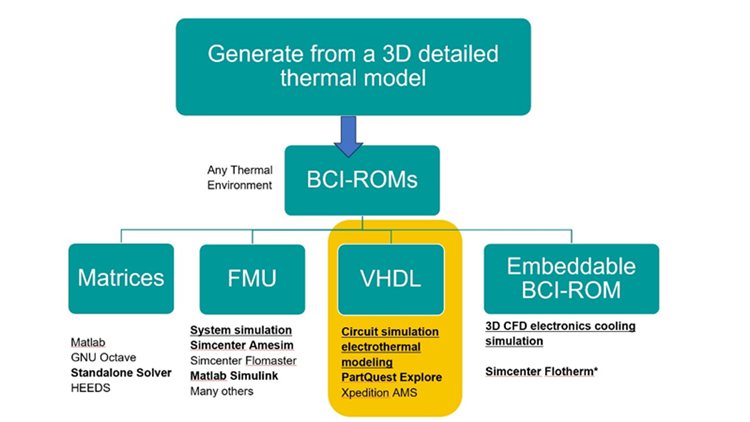
2. What other types of BCI-ROM are there, how are they used?
This image below explains the multiple formats of BCI-ROM that are possible to generate from a 3D detailed linear conduction model using several Simcenter fluids and thermal 3D CFD software tools. The presentation focuses on generation of BCI-ROMs in VHDL-AMS format for use in circuit simulation.
3. To use a BCI-ROM which simulation software do I need?
Circuit simulation use of a BCI-ROM in VHDL-AMS format: Only licenses or access to a suitable circuit simulation is needed. For electro-thermal simulation, you can import a VHDL-AMS BCI ROM model file and its associated data file (.csv format) and connect it directly into your electro-thermal circuit. This means you can upload BCI-ROM models into PartQuest Explore model for cloud-based design concept exploration, or you can use them directly in Siemens Xpedition AMS.
Creating a BCI-ROM: To create a BCI-ROM in VHDL-AMS format from a 3D analysis model, an additional module license is required. Note that is this is only for creation and export steps. So, if you are using Simcenter Flotherm or Simcenter Flotherm XT as a semiconductor OEM – then you need a license of the BCI-ROM module to generate these models that are subsequently used in other tools. Alternatively, if you are extracting a BCI-ROM from a detailed model in Simcenter FLOEFD, CAD embedded CFD software, then you do need the combined BCI-ROM and Package Creator module.
Other forms of BCI-ROM use: To use other types of BCI-ROM such as FMU format for system simulation, you would need 1D simulation tools that support that standard such as Simcenter Amesim or Flomaster. To use an Embeddable BCI-ROM model for 3D thermal analysis, you would need Simcenter Flotherm only. Please contact Siemens if you want to discuss how you can use these other types of BCI-ROM.
4. For the BCI-ROM component model shown – how did you generate the 3D package model before extracting the BCI-ROM?
The start point is a detailed model with all 3D geometry and materials defined. There are 3 primary ways you would create a detailed thermal model:
- You created a 3D thermal model manually
- You can leverage EDA data inputs. For example ODB+ data representing the package wafer layout can be imported from a tool like Xpedition Package Designer to speed up creation of a detailed Simcenter Flotherm model.
- Using Simcenter Flotherm Package Creator – a tool that has guided steps to create a number of packages from a library of common families and outputs a 3D CAD based model in minutes. The Package Creator is available in Simcenter Flotherm XT and Simcenter FLOEFD and can now output models for Simcenter Flotherm.
5. Where can I try out using a BCI-ROM?
For circuit simulation use of VHDL-AMS format BCI-ROM models that we focused on today, there are online articles with “Interactive” embedded application examples in PartQuest Explore:
- Article: Introduction to BCI ROM for Electro-Thermal Design
- Article: Electro-Thermal Design: Using BCI ROMs for Switch-Mode Power Electronics
You can make parameter changes to those designs and run new simulations, right in the context of those articles.
You can also create a free account in PartQuest Explore, and then create your own electro-thermal designs, and you can import and use any BCI ROM models that you create.
If you are talking about other types of BCI-ROMs used in other 1D simulation environments or 3D analysis, please contact us and we will direct you to the right information.
6. Why do I need to perform this “In Situ” calibration of component power losses in the circuit simulation, can’t I just use the losses published in the datasheets?
One problem is that a component datasheet may not provide information for the specific operating conditions of your circuit. You may be operating at a different gate voltage or at a temperature not covered in the switching or conduction loss graphs of the datasheet.
Also, dynamic interactions with other components in the circuit can affect a component’s losses. Examples include the gate driver turn-on delay, impedance or edge rate, and the reverse recovery characteristics of the free-wheel diode. All of these can have a significant impact on the power dissipation of the switching device. Calibrating each component’s losses using high-fidelity models and in the correct context of that application circuit can give more accurate power dissipation and temperature estimates in electro-thermal design.
7. What are the limits over which the “boundary conditions” can vary and the model still give good results?
The required accuracy is set by the engineer generating the BCI-ROM in Simcenter Flotherm or other tools. They set the acceptable relative error when the Embeddable BCI-ROM is extracted. A heat transfer coefficient (HTC) range is set by the user on extraction. It is up to the creator to set an HTC range that is sufficient to encompass conceivable use cases for a component.
From the circuit simulation environment user perspective, you specify the thermal resistance that is seen at each heat transfer face of the BCI ROM, as a design parameter for the electro-thermal system. This Rth value corresponds to a heat transfer coefficient and the known surface area of that face.
The generated model specifies a range of Rth values over which the original required accuracy is maintained. That range is typically 8 or 9 orders of magnitude. For example, a model face may be valid from 1 milli-degC/Watt up to 1 meg-degC/Watt! This gives the user that ability to specify, at that circuit or system level, whether that face has a great thermal connection to an external heat sink, or rather has a great insulator to prevent heat transfer in that direction. If the user provides a value of Rth that is outside of this valid range, the model will issue an error message so the user can change it to an appropriate value.
8. Embeddable BCI-ROM for 3D thermal analysis. What is that separate file type? and how does that compare to DELPHI compact thermal model or a detailed model in 3D analysis?
The file type for the Embeddable BCI-ROM type is “.erom”. As of Simcenter Flotherm 2310, you can generate this file (requires BCI-ROM module license). All Simcenter Flotherm users can import and use an EROM without needing an additional module from the 2310 version onward
Comparing Embeddable BCI-ROM to other types. First off, BCI-ROMs for circuit simulation tools solve extremely quickly. The separate Embeddable BCI-ROMs for 3D analysis differ in that their value is in accuracy while protecting sensitive IP physical details that cannot be shared across organizations in the supply chain. Comparing solve times of Embeddable BCI-ROMs , they do vary depending on complexity of the model. Comparing accuracy, Embeddable BCI-ROMs are typically well under 5% error compared to the 3D detailed thermal model results (with <2.5% error being often achievable). This offers an accuracy level that is comparable, or far better, to the standard DELPHI compact model approach. The clear differences to DELPHI and 2-resistor modeling is that Embeddable BCI-ROM supports transient analysis and multiple powered heat sources within a package. You can find out more about Embeddable BCI-ROMs in this blog.
When using a BCI-ROM for circuit simulation (VHDL-AMS format) there is very high accuracy compared to the 3D detailed model as inputs are simpler and constrained compared to any 3D analysis obviously.