Listening to your future product: CAD-centric FRF testing and Virtual Point Transformation
What’s New in Simcenter Testlab Neo 2306?
In the ever-evolving landscape of product development in the context of noise and vibration, a remarkable transformation is underway – one that is reshaping the way industries conceptualize, design, and test their innovations.
Gone are the days when physical prototypes dominated the scene, consuming time, and resources, and often leading to extensive trial-and-error cycles. Instead, a paradigm shift is taking place, championing the era of digital twins and predictive capabilities. This allows component suppliers to demonstrate how their products will sound without having to physically integrate them into their customer vehicles.
At the forefront of this transformation lies the concept of “System NVH Prediction” – a revolutionary approach that demands accurate and efficient Frequency Response Function (FRF) measurements. These transfer functions are used to represent each sub-system in a modular way.
This article delves into the fascinating journey of this ongoing evolution of reducing their reliance on physical prototypes. Join us as we unravel the pivotal role of FRF measurement in this journey toward enhanced efficiency, precision, and unprecedented foresight.

Figure 1 – System NVH Prediction Flowchart
Mirror your test setup virtually
Accurate measurement of setup geometry stands as a cornerstone for reliable testing, yet practical measurement constraints often introduce potential inaccuracies. Inaccessible measurement locations limit data collection comprehensiveness.
The reduced prototype availability and the necessity to compare test and simulation results for validation, alongside preparing and fully documenting the setup adds layers of complexity.
Finally, one needs to ensure uniformity in sensor naming and positioning across the entire organization – between simulation and test.

Figure 2– Virtual instrumentation of a gearbox
Enter virtual instrumentation – a transformative approach enabled using CAD models to drive the data acquisition process and analysis. Through this approach, engineers can overcome these challenges. Since prototypes are only available for a limited time, the CAD geometry allows the engineer to prepare and optimize his measurement setup upfront.
The virtual instrumentation process involves integrating the use of CAD models into the entire data acquisition process, virtually instrumenting the test objects and specifying the sensor data. This allows the engineer to mirror and prepare real-world test setups

Figure 3 – CAD centric transfer function measurement process
The wealth of information extracted from these setups aids the measurement engineer in precisely defining the optimal setup for the required FRF characterization. Highlighting potential issues, minimizing errors, and enhancing the alignment between intended and realized configurations.
Throughout the measurement process from the setup, impact acquisition and validation, the virtual instrumentation can be used as guidance.
Video – Virtual instrumentation
Use Virtual Point Transformation for precise alignment
One of the challenges faced revolves around obtaining Frequency Response Functions (FRFs) from unmeasurable locations and in various directions, encompassing both rotational and translational degrees of freedom.
Dedicated excitation software (Simcenter Testlab) and hardware (Simcenter Qsources) have been developed to be able to perform measurements in very confined areas, for example, in the fully packed electric drive unit compartment.
Nevertheless, in some places, the engineer can just not perform these precise measurements with the right excitation. The complex mathematics of the modular System NVH prediction method require that the interface points be precisely defined to avoid inconsistencies in the measured FRF data.

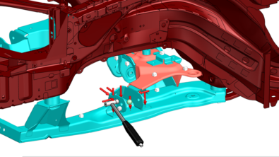
Figure 4 – CAD centric impact testing
Building on top of the virtual instrumentation, the Virtual Point Transformation method can overcome this issue. The user defines the virtual points with each of their indicator sensors.
The process involves automatic computation of Virtual Point FRFs, utilizing the measured transfer functions from the assigned indicators. The validation process is made easy using intuitive quality indicators, ensuring the reliability of the computed data. This is especially beneficial if the data will be used in the context of Source characterization with Component-based Transfer Path Analysis (CTPA), Frequency based substructuring (FBS), and correlation with simulation models (CAE).
Figure 5 – Virtual Point Transformation
Links for more information
Simcenter Testlab Virtual Prototype Assembly:
https://webinars.sw.siemens.com/en-US/predict-vehicle-nvh-performance
https://blogs.sw.siemens.com/simcenter/vpa-for-vehicle-nvh-prediction/
https://blogs.sw.siemens.com/simcenter/electrification-the-new-pressure-on-tire-manufacturers/
https://blogs.sw.siemens.com/simcenter/take-control-of-pass-by-noise-with-a-virtual-prototype/
https://blogs.sw.siemens.com/simcenter/vehicle-nvh-integration-how-to-combine-test-and-simulation/
https://blogs.sw.siemens.com/simcenter/4-steps-to-predict-road-noise-a-project-with-hyundai-motor-group/
https://blogs.sw.siemens.com/simcenter/simcenter-testlab-2206-scalable-data-management/
https://blogs.sw.siemens.com/simcenter/simcenter-testlab-2206-vpa/
https://webinars.sw.siemens.com/en-US/component-based-transfer-path-analysis/
https://mobex.io/webinars/road-noise-prediction-an-mbse-approach-to-virtual-nvh-development/
Simcenter Testlab NVH Simulator:
https://webinars.sw.siemens.com/en-US/master-sound-perception-using-vehicle-sound-simulator/
https://blogs.sw.siemens.com/simcenter/why-a-vehicle-sound-simulator-can-help-you-define-what-should-come-after-vroom/


