Technical and economical assessment of a Solid Oxide Fuel Cell (SOFC) Combined Heat and Power residential system using System Simulation
In today’s global race for energy decarbonization for a net-zero target in 2050, governments and industries are facing the challenge of finding achievable and cost-effective solutions.
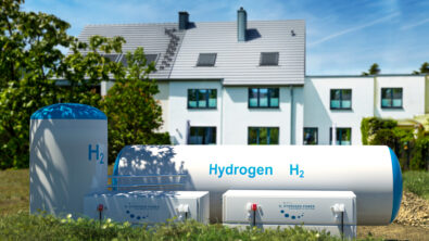
With the emergence of hydrogen as an alternative clean fuel, the Solid Oxide Fuel Cell (SOFC) is seen as a promising power generation technology, especially for residential applications that are already connected to the natural gas network.
To achieve high efficiencies, SOFCs are usually part of a Combined Heat and Power system (CHP), thanks to their operation at high temperatures, thus enabling to use waste heat for water and space heating but also cooling if linked to an absorption and adsorption machine.
The capability of SOFCs to run with different fuels such as natural gas, methanol, or directly hydrogen, offers a high flexibility and adaptability of the solution in terms of fuel usage, local supply specificities as well as evolution in time.
The objective of this article is to show a system model of a complete SOFC m-CHP (micro-CHP) residential system based on a yearly consumption profile to compare the cost and emissions of such a system with different energy mix scenarios.
SOFC principle and main characteristics
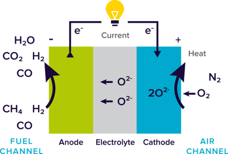
A fuel cell, whatever the technology used, is a system producing electricity through an electrochemical reaction. In this redox reaction, hydrogen and oxygen are combined, generating electricity, heat, and water. The 2 electrodes, i.e. anode and cathode are separated by an electrolyte enabling the transport of ions from one electrode to the other. Figure 1 below illustrates this principle.
While main fuel cells are directly fed with pure hydrogen, SOFCs are fuel flexible and can be fed for instance with biofuels (e.g., methanol, ethanol), biogas, syngas but also with more traditional fossil fuels such as natural gas.
In that case, a catalytic fuel reforming process (internal or external) is part of the system.
Another key characteristic of SOFCs is the high operating temperature, which is between 700 and 1000°C, thus giving extended possibilities for cogeneration or CHP. This increases the system efficiency up to 90%. On the other hand, it adds a transient constraint, especially when considering the start-up time and variable loads.
A non-neglectable advantage though, is the capability of SOFCs to be reversible and to work consequently in electrolyzer mode. In that case, we talk of reversible Solid Oxide Cell (rSOC) and this is what will be released in the upcoming SimcenterTM AmesimTM 2310 version.
rSOC and reformers models overview in Simcenter Amesim
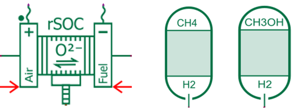
In order to handle SOFC-based systems, 3 components will be released in Simcenter Amesim 2310 (see Figure 2):
- A scalable rSOC component based on the Butler Volmer electrochemical equations, enabling the prediction of the activation, ohmic, and concentration losses, considering both H2 and CO as fuels.
- 2 steam reforming and water gas shift components for methane (including an autothermal option) and methanol, using default literature-based reaction kinetics (with a user-defined option).
Hereafter we can see unitary validations of these components.
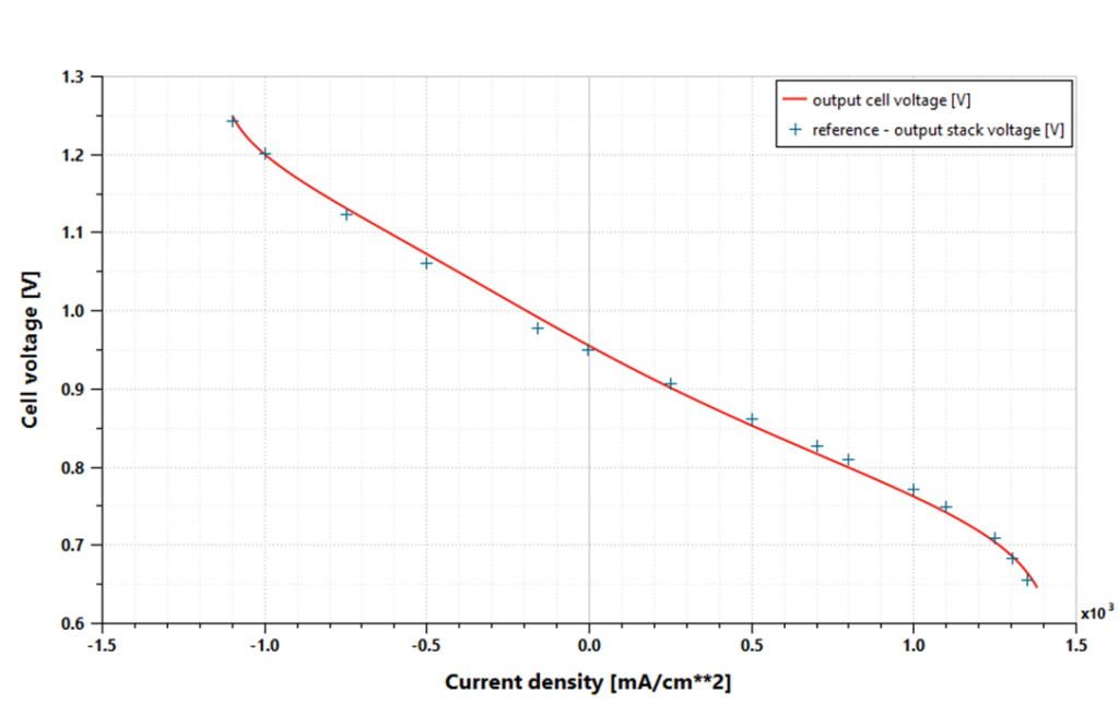
Figure 3 shows the entire polarization curve (negative current for electrolyzer mode). This curve has been made at 850°C, 50% H2 & 50% H2O at anode, 100% O2 at cathode and a fuel utilization of 68%. This simulation result is compared with Ref 1.
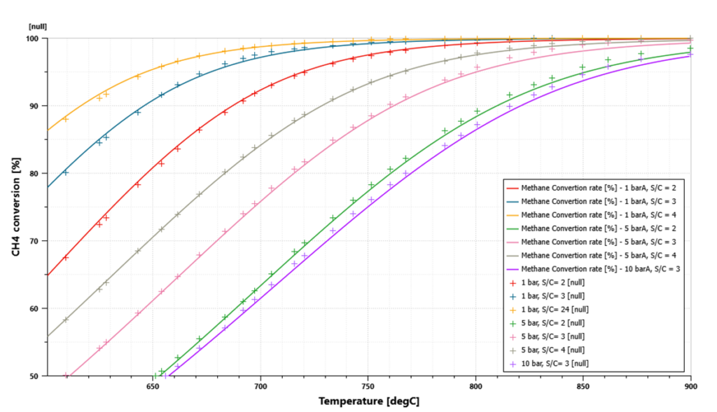
Regarding the reformer, the Figure 4 shows for a steam methane reformer the evolution of the CH4 conversion rate in [%] as a function of the temperature in [degC] for different steam-to-carbon ratios and different pressures. Results are compared with Ref 2.
Application example: modeling of a residential SOFC m-CHP system in Simcenter Amesim
As mentioned previously the 2 main advantages of SOFCs are:
- Fuel flexibility
- High efficiencies when considering co-generation
This makes it a good candidate for residential systems or even datacenters where both electrical and thermal energies are consumed under variable loads depending on usages but also on ambient conditions. The continuity of the energy supply is of course of primary importance but efficiency, energy sources, and storage have a direct impact on costs and CO2 equivalent emissions.
Hence system simulation imposes itself as a pragmatic and quick way of sizing and analyzing such a system. We can list several outcomes from system simulation, among them:
- Cost optimization through grid balancing
- System efficiency optimization (cogeneration, CHP, energy storage, …)
- System and components control optimization
- System and component sizing based on statistical weather data and system location
- Production prediction based on weather forecast (wind, temperature, solar irradiance, …)
- Analysis of the various options that will determine the economic and operable feasibility of a selected design
- Safety / standard operations: what if scenarios/start-up & shutdown procedures
As an illustration, a SOFC m-CHP model demonstrator for a residential application has been built in Simcenter Amesim to simulate different scenarios of a home energy demand response.
Figure 5 below shows a schematic of the system.
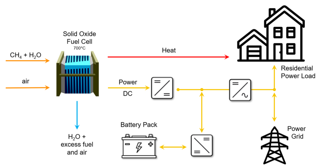
The system comprises:
- a SOFC/reformer fed by natural gas that will generate electricity and provide heat for the house
- a battery pack for electricity storage to absorb the power load variability
- a connection to the grid to exchange power when the demand exceeds or is below the system capacity
The corresponding Simcenter Amesim model is presented in Figure 6 below:
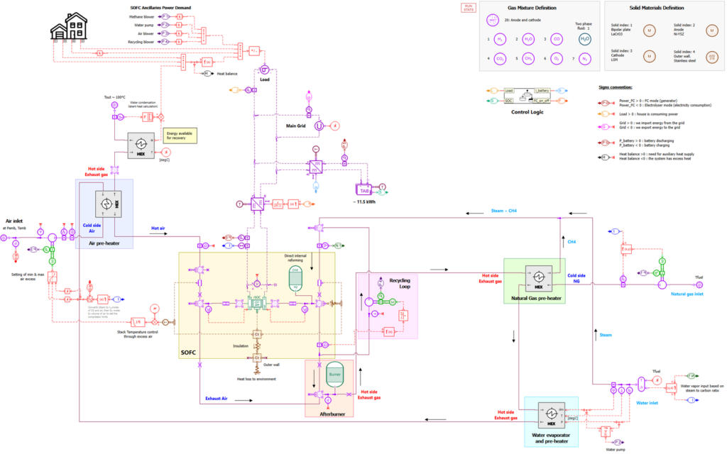
The main elements of the system are the following:
- A natural gas supply (upper right)
- A gas pre-heater and a water evaporator connected to the SOFC fuel exhaust line
- A SOFC, a steam methane reformer and an afterburner
- A DC electric bus connected to the battery, the grid, and the house
- An air pre-heater and a house heat exchanger (for water and space heating) connected to the SOFC fuel exhaust line
- A logic state controller to supervise the system
We can see that the system model is multi-physics by nature, combining electrical, gas, water, chemical, electrochemical and thermal domains, thus giving the possibility to perform transient analyses with variable boundary conditions and considerations of subsystems’ interactions.
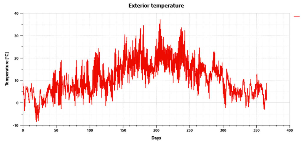
After an initial sizing of the different components, a yearly simulation based on existing residential power load and exterior temperature profiles (from Ref 3) has been performed.
The 2 figures below show the evolution over a year of the exterior temperature (Figure 7) and of the house power demand, fuel cell, battery, and grid powers as well as of the battery State of Charge.
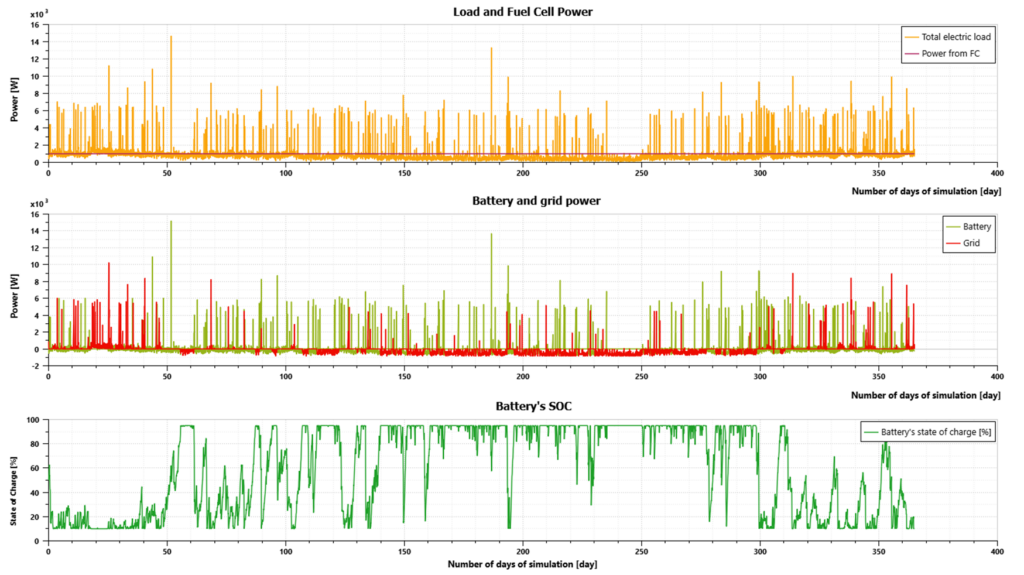
As can be seen, the main assumptions of the model are the following:
- SOFC constant load: due to the low dynamics of such a system (high temperature), which is the case of most of today’s similar systems, but the model is not limited to constant loads, and we can take advantage of the model capability to do transients to study for instance warm-up/start-up and shutdown phases
- The exterior temperature is used to calculate the heating and cooling space requirements to maintain a temperature in the house of 20°C in winter and 22°C in summer
- Depending on the power demand level, the power can be delivered by the SOFC, the battery or the grid but can also be delivered to the grid and/or the battery for low power demands
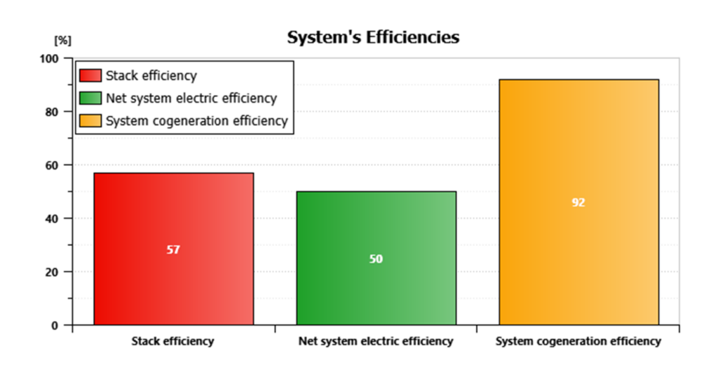
Looking globally at the efficiency of the SOFC system (Figure 9), we see that we achieve a standard efficiency of 57% considering the stack alone but an efficiency higher than 90% considering the SOFC with m-CHP.
At the end, this study offers 2 valuable outcomes that we will further describe:
- Energy cost estimation
- CO2 equivalent emissions
For these estimations, we propose different scenarios and assumptions that we will apply for 2 European countries, France and Germany (using the same temperature and load profiles).
Regarding costs, we are considering the retail price of natural gas and electricity in each country as of December 2022 and for the CO2 equivalent emissions, the energy mix of each country. Scenarios compared are the following:
- SOFC m-CHP scenario as described in this article
- Energy supply from the grid only
- Energy supply from the grid for electricity and gas for space and water heating
- Energy supply with pure green hydrogen with a current estimated cost per kg
- Energy supply with pure green hydrogen in 2030 with an estimated cost of 5€ per kg H2
To summarize the price and energy mix assumptions, see the Figure 10 below:

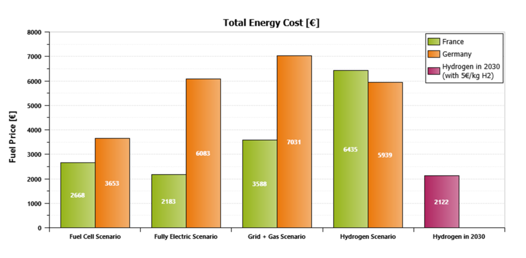
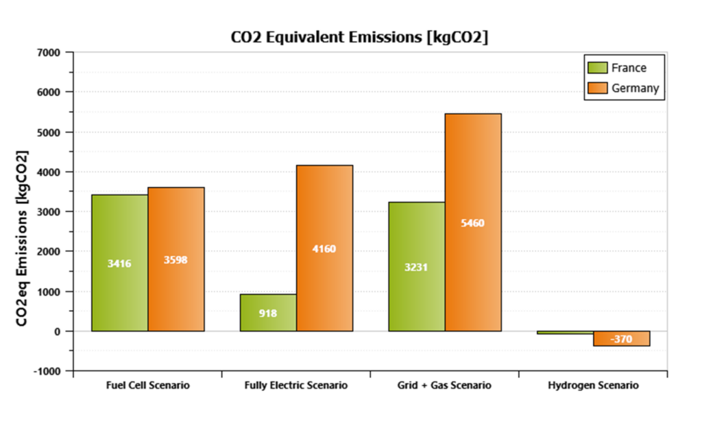
We see from the above figures that the SOFC m-CHP system is today the best current scenario for Germany in terms of costs and CO2 emissions, whereas the full electric one is the best for France thanks to the large nuclear part in the energy mix.
The hydrogen scenario, considering green hydrogen only is the most expensive one as of today but is very promising at the 2030 horizon if the objective of 5€/kg H2 can be reached.
Note that we expose negative CO2 emissions with the hydrogen scenario, considering the part of green hydrogen that is sent to the grid.
Conclusion and perspectives
We have demonstrated that system simulation is a great asset in designing and sizing your SOFC-based energy system. This enables to quickly estimate and compare with other energy systems architectures the associated costs and CO2 emissions.
Variability of ambient and operating conditions such as pressure and temperature are considered in the level of models presented, thus enabling energy production, storage, and exchange with the grid forecasts.
This type of model can also be used for warm-up/start-up and shutdown scenarios.
I’d like to thank Sthefi Klaus who made most of this model during her internship at Siemens SISW in Lyon, France and as part of her Densys master thesis with the support of Colas Flament and myself.
Stay tuned, we will soon release another article presenting a green microgrid system with solar panels, PEM fuel cell and electrolyzer, H2 and battery storage systems.
Want to learn more about Simcenter Amesim hydrogen-related topics?
You can watch the following webinar:

propulsion system
using a simulation-based approach
Or read the following blog posts:


References
Ref 1 : Designing and analyzing an electric energy storage system based on reversible solid oxide cells, Alessandra Perna, Mariagiovanna Minutillo, Elio Jannelli, Energy Conversion and Management 159 (2018) 381–395
Ref 2 : Conversion of hydrocarbons and alcohols for fuel cells, F. Joensen and J. R. Rostrup-Nielsen, Journal of Power Sources, vol. 105, no. 2, pp. 195–201, Mar. 2002, doi: 10.1016/S0378-7753(01)00939-9.
Ref 3 : M. Schlemminger, T. Ohrdes, E. Schneider, and M. Knoop, “Dataset on electrical single-family house and heat pump load profiles in Germany,” Sci Data, vol. 9, no. 1, Art. no. 1, Feb. 2022, doi: 10.1038/s41597-022-01156-1