Hydrogen: Charge your long-range Electric Vehicle in less than 5 minutes

Introduction
One of the main constraints of battery electric vehicles (BEVs), especially the ones using large battery packs to reach an acceptable the range, is the time to recharge batteries. That forces the driver to stop a long while during a long trip with a passenger car or a truck. In case of a forklift or an excavator, it makes the device non usable until the battery is charged again. Integrating a fuel cell inside the Electric Vehicle instead of the battery or more frequently in combination with the battery helps solve the problem. To recharge the vehicle, you just have to refill the tank with hydrogen, an operation that can be non-longer than 5 minutes for a passenger vehicle or 10 to 15 minutes for a long-haul truck. Toyota, for instance is claiming that the Mirai tank can be refilled in less than 5 minutes for a 650 km range.
Let’s use Simcenter Amesim to evaluate the refueling time of a Fuel Cell Electric Vehicle (FVEV), comparing different system architectures. The model can also be used to predict how much energy is consumed to compress the hydrogen and size the cooling systems used to keep the gas at the right level of temperature during its compression.
Modeling the refueling station
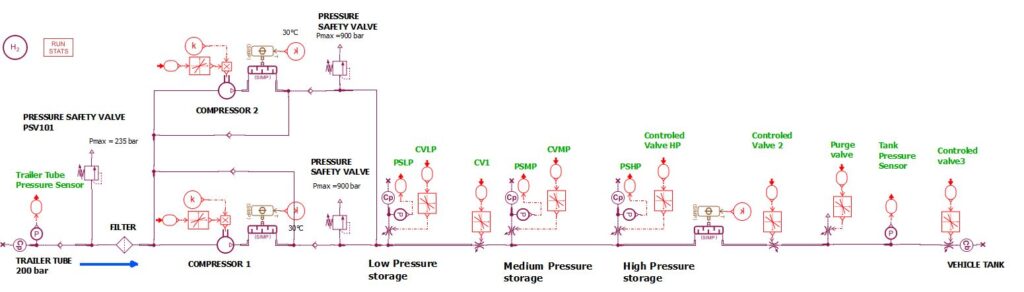
Fig. 1: System model
Hydrogen source
Refueling stations can produce their hydrogen locally, for instance using a combination of solar panels with an electrolyzer. Another alternative is that hydrogen is produced with a larger electrolyzer system to reduce the cost and then transported to the refueling station, for instance using a tube trailer. We will consider this later case in our model with the following assumptions:
- Tube trailer tank volume: 5 m3
- Initial pressure: 200 bar
- Initial temperature: 20°C
In these conditions, the initial quantity of hydrogen in the tube trailer is close to 76 kg.
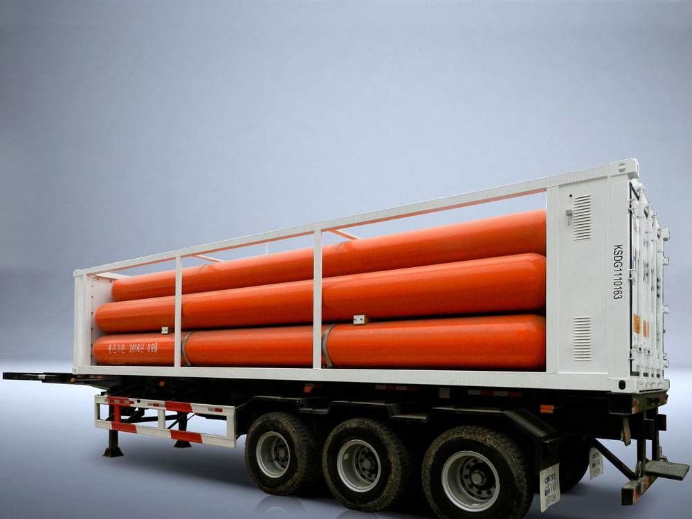
Fig. 2: Tube trailer
Vehicle tank
For the vehicle tank, we will consider the case of a passenger vehicle with the following assumptions:
- Tank volume: 150 L
- Initial pressure: 50 bar
- Final expected pressure: 700 bar
- Initial temperature: 20°C
At 700 bar this tank will contain close to 6 kg of hydrogen.
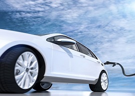
Fig. 3: FCEV
Hydrogen compression system
To fill the hydrogen from the trailer tube pressurized at 200 bar to the vehicle tank expected pressure at 700 bar, the system is using 2 volumetric compressors operating in parallel with the following assumptions:
- Compressor displacement: 150 cm3/rev
- Compressor rotary velocity: 120 rpm
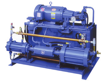
Fig. 4: Compression system
Thermal management
To keep the system safe, increase the quantity of hydrogen stored in the tank and avoid high temperatures that would damage the vehicle tank liner, several heat exchangers are integrated in the system. In our case, we assume that heat exchangers are integrated:
- at the outlet of compressors to cool hydrogen down to 30°C after compression
- upstream the vehicle tank to supply hydrogen to the vehicle tank at a temperature close to -50°C.
Hydrogen buffer tanks
Low-pressure, medium-pressure and high-pressure tanks are integrated in the system. They can be used to reach several purposes:
- Speed up the vehicle tank refilling
- Downsize compressors or reduce their operating speed
- Reduce the warming up of hydrogen during compressions and then downsize cooling systems
The buffer tanks are fined as follows:
- Low-pressure tank
- Initial pressure: 380 bar
- Volume: 500 L
- Medium-pressure tank
- Initial pressure: 580 bar
- Volume: 300 L
- High-pressure tank
- Initial pressure: 850 bar
- Volume: 300 L
Controls
Controls strategies are used to control the compressors and system valves. Strategies are based on a state controller. The state transitions are mainly driven by the value of pressures in the tube trailer, the buffer tanks and the vehicle tank.
Roughly, when the vehicle tank is connected to the refueling system, valves are opened to smoothly equilibrate the vehicle tank pressure with the one of the tube trailer. Then, the compressors can be activated or the buffer tanks can be used.
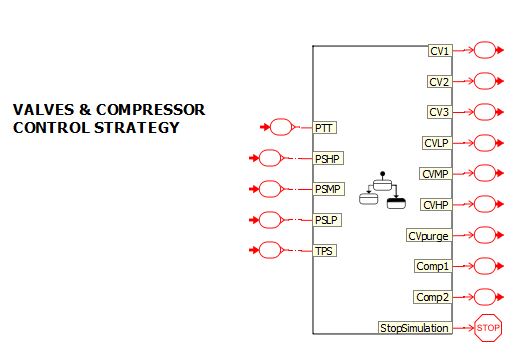
Fig. 5: Valves and compressors controls
Hydrogen
In the whole system, the hydrogen flow, pressure, temperature and thermodynamic properties are predicted using a real gas model (Peng-Robinson).
First case: Refilling the vehicle tank without using the buffer tanks
Using our system model, we can simulate the refilling of the tank, using the hydrogen from the tube trailer and the 2 compressors. The valves of the buffer tanks are remained closed during that process. The simulation is stopped once the vehicle tank pressure reaches the expected pressure: 700 bar.
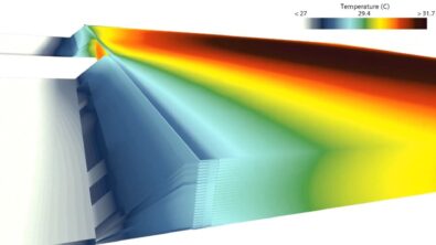
A first interesting way to analyze simulation results within Simcenter Amesim is using the Sketch animation. Sketch animation makes it possible to visualize on the model sketch the dynamic evolution of pressures or temperature all along the scenario and in the different part of the system (Fig.6 and Fig.7).
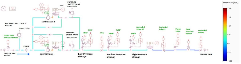
Fig. 6: Sketch Animation of the temperature repartition in the system
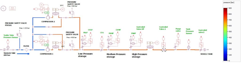
Fig. 7: Sketch Animation of the pressure repartition in the system
Analyzing deeper the simulation results, we can also identify that:
- The tank refueling time is 8 minutes and 40 seconds (Fig.8).
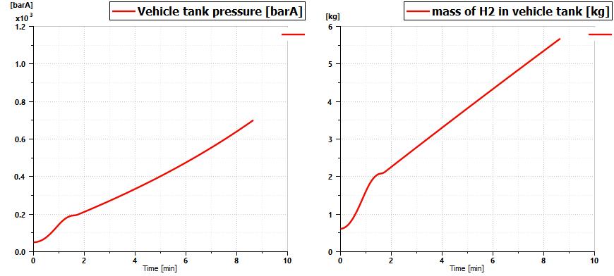
Fig. 8: Evolution of tank pressure and hydrogen mass in the vehicle tank
- The maximum power consumed by the 2 compressors is close to 17.3 kW and the energy consumed by these compressors is close to 1.1 kW.h (Fig. 9).
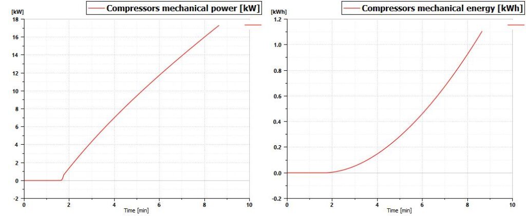
Fig. 9: Evolution of compressors power and energy consumption
- The 2 heat exchangers integrated downstream the compressors must be able to extract some heat corresponding to 6.4 kW when the heat exchanger integrated upstream the vehicle tank must be able to extract 26 kW (Fig.10).
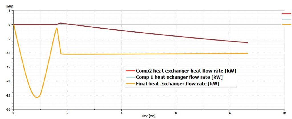
Fig.10: Heat flow rate of heat exchangers
These results are interesting and charging our FCEV in 8 minutes is already much faster than recharging batteries of a BEV. However, it is not really satisfying as the purpose is to be able to refill the tank of a passenger car tank in less than 5 minutes.
Different possibilities can make it possible to reach this target:
- We can for instance modify our model and check that a system with 4 compressors with their own heat exchangers would be able to fulfill the requirement. But that would generate a more complex and more expensive system.
- The model can also be used to identify that increasing compressors displacement to 320 cm3/rev also make it possible to refill the vehicle tank in less than 5 minutes. But still, we will need to extract more heat with heat exchangers located downstream the compressors (14 kW) and bigger compressors and heat exchangers will be more expensive and will certainly generate more noise.
- Another quite simple alternative would be using buffer tanks. That’s what we will consider in the second scenario.
Second case: Refilling the vehicle tank using the buffer tanks
Using the same system model than previously, it is possible control valves to take benefit of the buffer tanks.
Once the vehicle tank pressure is close to the trailer tube one (200 bar), the control strategy actuates the opening of the valve connected to the low-pressure buffer tank (380 bar). Once the vehicle tank pressure is balanced with the one of this buffer tank, the valve is closed again and it is the turn of the valve of the medium buffer tank (580 bar) to be opened. Finally, when the vehicle tank pressure is balanced with the one of the medium-pressure buffer tank, the valve is closed again and the valve of the high-pressure tank (850 bar) is opened.
When the vehicle tank is filled at 700 bar, the compressors are finally used to re-establish the buffer tank pressures at their initial level.
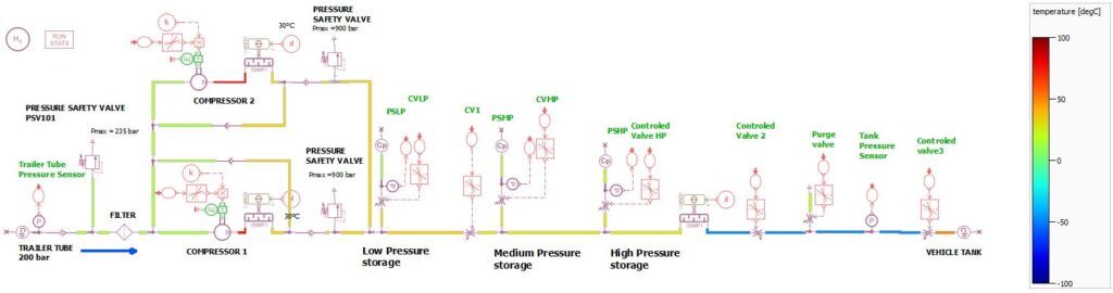
Fig.11: Sketch Animation of the temperature repartition in the system
Once again, we can use the sketch animation to visualize, all along the scenario, the dynamic evolution of pressures or temperatures in the different parts of the system (Fig.11).
We can also identify that using the buffer tanks, the system is now able to refill the vehicle tank faster than five minutes. So, the target is reached: the FCEV is charged in a time like a conventional gasoline vehicle! Three additional minutes are then used by the system to re-compress the hydrogen in buffer tanks to their initial pressure.
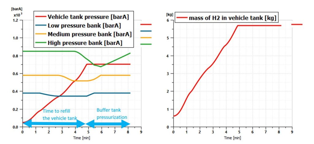
Fig.12: Sketch Animation of the temperature repartition in the system
However, we can notice that, as a drawback of this case, the compression now requires more power (up to 20 kW) and energy (1.5 kWh). This can mainly be explained by the need to compress hydrogen to 830 bars in the high-pressure buffer tank (Fig.13).
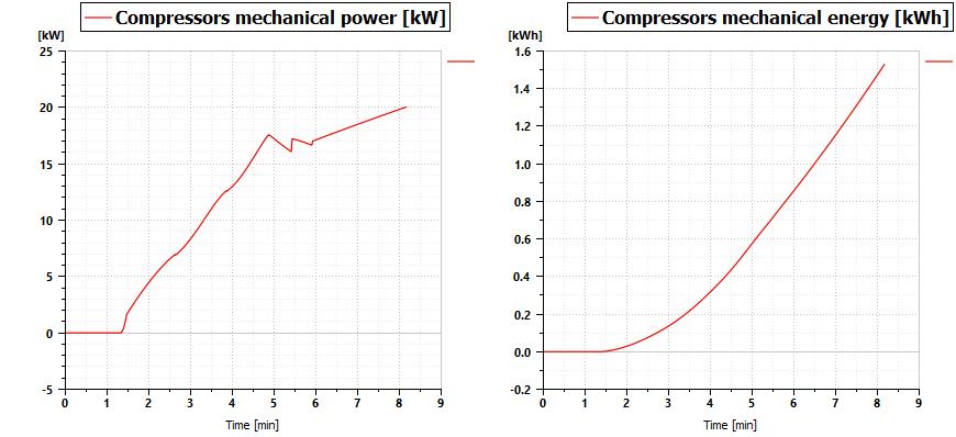
Fig. 13: Compression power and energy using the buffer tanks
On the other hand, there is almost no impact on the sizing of the cooling system as the maximum heat power that will need to be extracted is quite similar (Fig.14).
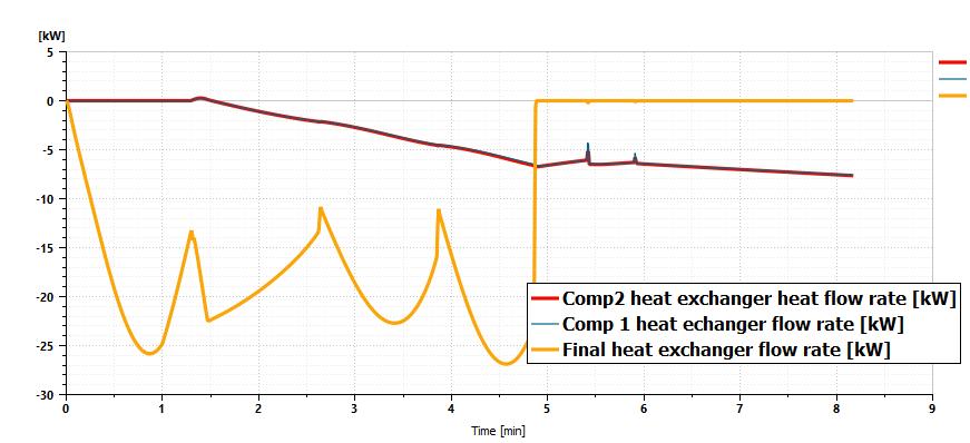
Fig. 14: Heat flow rate of heat exchangers with buffer tanks
Conclusions
System simulation with Simcenter Amesim helps to design hydrogen refueling stations. With fast simulation time (The CPU time for the simulation described above is less than 1 second using a standard laptop), it is easy and quick to evaluate different technical solutions regarding the architecture of the system, the sizing of the sub-systems or control strategies. With advanced post-processing tools, it is also easy to analyze simulation results and the physical behavior of the refueling station, especially regarding the dynamic evolution of the hydrogen flow, pressure and temperature in the different locations. So, that really helps to design the best system at the 1st attempt, making it possible to refill vehicle tanks as quick as possible, but also controlling the hydrogen temperature or the power that will be consumed for the compression of the gas and the thermal management.
If you want to download the Simcenter Amesim demo model used to write this blog, click here.
Check out Simcenter Amesim free trial to experience the features for yourself!
What to read next:
Comments
Leave a Reply
You must be logged in to post a comment.
Very nice… I really like your blog. Very useful information.