Safety: The price for long range and high performance in electric vehicles?
Long before anybody thought about battery simulation, the first electric car reached 100 kph (62 mph) and set the velocity world record in 1899. Ironically, it looked like a big artillery grenade on wheels. This explosive design of the car with the sad name “la jamais contente” (“the never happy”) could be interpreted as a symbol for an unpleasant truth in electromobility: The higher the range and electric performance of a battery, the more explosive is its behavior in case of an accidental destruction.

The worst case scenario that can happen to a battery is the so-called thermal runaway. It describes several exothermic reactions that release a huge amount of energy in a very short time: How it looks like? Fire, explosions and in the end a charred melted mass that once was an electric car. The mechanisms that can induce such a catastrophic event are overheating or short circuiting the battery cells.
Is battery safety the price we have to pay to drive long distances?
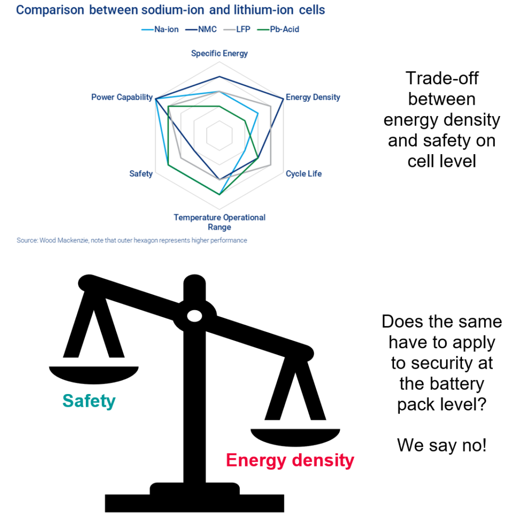
The good news is, there are some safe and environmental friendly cell chemistries available like LFP (Lithium-Iron-Phosphate). Na-ion (sodium) might be introduced to the market as well this year for automotive applications by companies like CATL or BYD. Batteries using these chemistries don’t start to burn due to mechanical damage like for example a nail penetration. The bad news are: The energy density of the safe alternatives is much lower than for chemistries in the higher car segment like NMC (Lithium-Nickel-Manganese-Cobalt-Oxide) or NCA (Lithium-Nickel-Cobalt-Aluminum-Oxide) and their applications will be restricted for cars with limited range and performance. Pure sodium batteries could be good and sufficient for inner city mobility, but not the right choice for going on vacation in a country with just a few, widely scattered charging stations.
Mixing sodium battery cells with additional battery cells with higher range and performance chemistry cells could be a good compromise, but cells with very high performing cell chemistry like NMC or NCA raise the safety issue again. So is battery safety the price we have to pay if we want to drive long distances?
The answer is no! Safe battery designs are possible, even for high power battery chemistry if safety requirements are taken into account during the design process. The most efficient way to do this is a combination of modern battery simulation techniques, combined with experimental tests. This safes time, costs and most important: It can save lifes!
Simulation in modern battery development
Simulations have become the backbone of modern battery design engineering. They help to identify dominant parameters that impact a system, select the best design and find the optimal adjustment of various system parameters. Key to success is an efficient combination of the right battery simulation techniques at the right time in the design process.
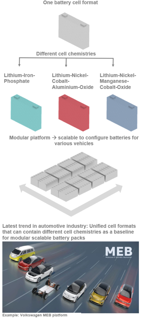
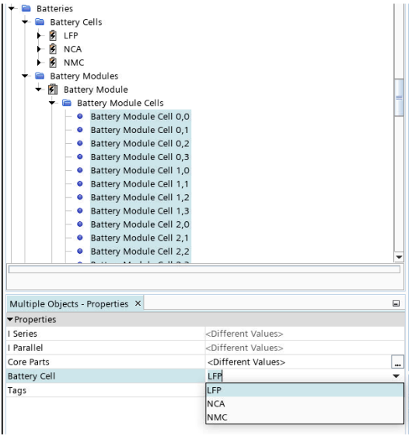
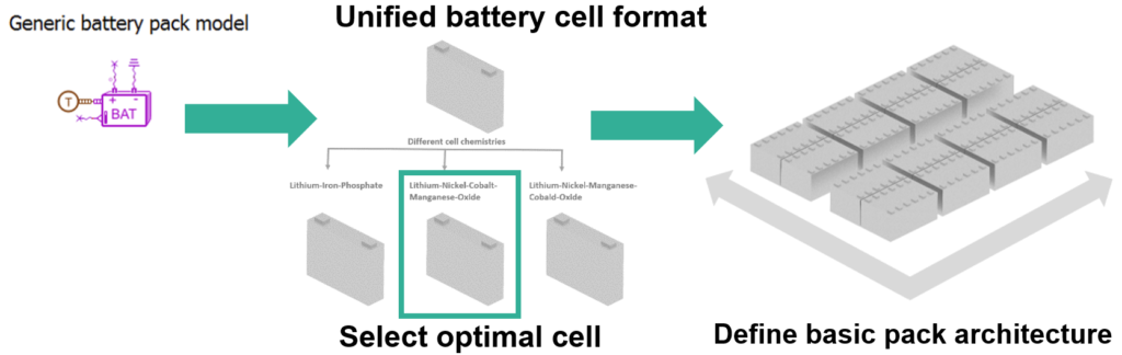
In order to save costs and use synergies wherever possible, there´s a trend in the automotive industry to use unified battery cell formats, that can contain different cell chemistries. The cells are integrated in a modular platform that can be scaled to achieve different battery pack configurations.
Despite this efficient approach on the platform level, there is a persistent classic mistake during the design process of a battery: That is to account too late for the safety critical topic of thermal runaway.
Battery tests are very expensive and due to the high requests, it can be difficult to get a slot in test facilities that can perform thermal runaway tests. In addition, many engineers don’t know how to simulate thermal runaway or lack sufficient software tools to perform these battery simulations. As a consequence, the battery design starts and includes often not more than only a CAD part with a guessed size for a thermal runaway protection material like a heat shield or an insulating foam. For the venting system that shall release the pressure and the hot gases in case of a thermal runaway, the CAD engineer draws a circle that should represent a burst disc, but if the size is sufficient and if one disc is enough no one knows at that point. Different teams start in parallel to develop the battery components like the cooling loop, the battery management system or the casing.
The bad surprise comes with the first thermal runaway test late in the timeline: If the battery does not fulfill the officially requested thermal runaway requirements, the the dimensioning of all parts from all teams has to be started from scratch. Congratulations if you are the chosen one to communicate the bad news to upper management!
To avoid those late surprises, Simcenter STAR-CCM+ developed a new battery simulation workflow, that allows to switch easily between electrothermal battery simulations and thermal runaway simulations. The user can work on the electric performance, the battery cooling loop, the thermal runaway protection material and the venting system in only one battery simulation model. That enables the user to scale battery platforms with different cell chemistries easily with respect to their individual physical properties.
Thermal runaway simulation in Simcenter STAR-CCM+
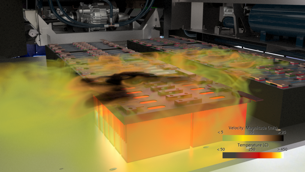
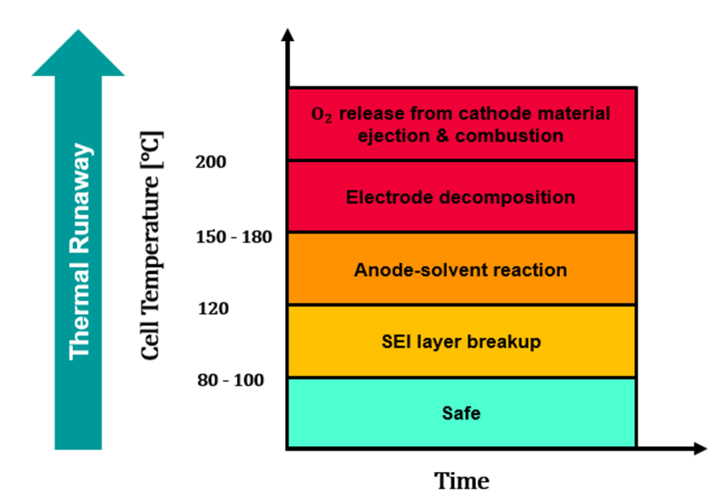
The thermal runaway of a battery is mix of different physical phenomena. If the cell receives a certain amount of energy, several chemical redox reactions take place and release large amounts of heat. The pressure inside the cell increases rapidly and at some point, the cell will eject the hot venting gases that can reach more than 1000° C. For a safe battery design, all of these effects have to be taken into account. Simcenter STAR-CCM+ offers a simple approach with high accuracy to model them.
Here’s how it works in a nutshell:
The released heat is divided into 2 mechanisms:
- The heat released by the venting gas
- The heat released by the solid cell parts
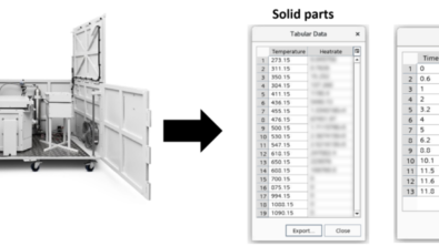
The input values for the battery simulation come from an experiment performed with a single battery cell in a so-called accelerated rate calorimetry (“ARC”) test. They consist of two tables:
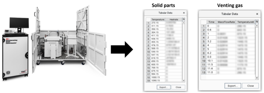
Combine heat release and equivalent circuit models in the User Defined Battery Cell
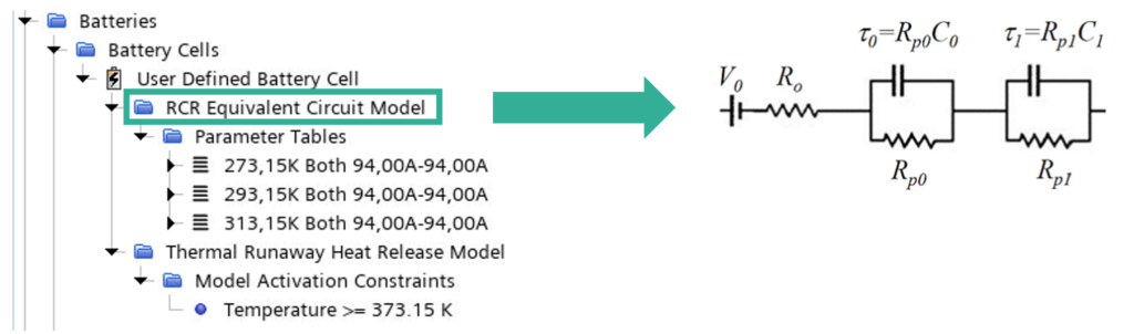
A new feature in the workflow of the Battery Simulation Module in Simcenter STAR-CCM+ is the Thermal Runaway Heat Release Model that describes the heat released by solid parts of the cell during thermal runaway. It can be added to the equivalent circuit battery model (= “RCR Model” in Simcenter STAR-CCM+).
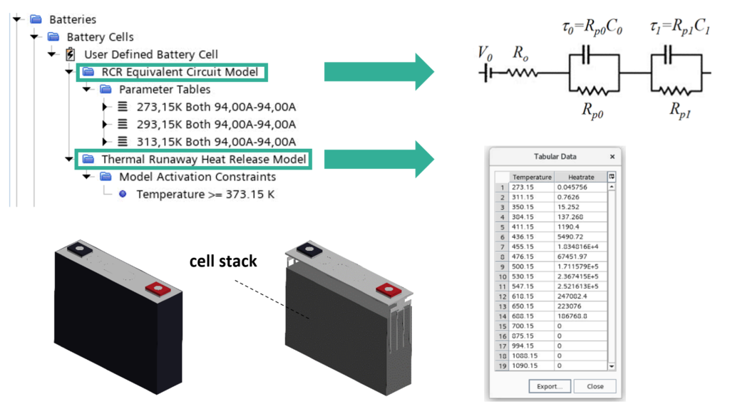
The heat release model is based on a table that contains the cell temperature [K] and the heat rate [W] of the solid cell parts as input parameters. The data can either come from an accelerated rate calorimeter (“ARC”-) test or be determined with the software Simcenter Amesim, that has some of the most common cell chemistry ARC-test data available in libraries and the values can be scaled according to the battery shape and capacity. The heat release is automatically activated for any part of a region that has a continua containing the battery model. The activation of the heat release can be specified by the user, for example by a specified temperature of the battery cell stack.
This easy set up enables the user to integrate thermal runaway safety aspects into the battery design from step one. The capability to parameterize geometries, perform intelligent design explorations and switch easily between different electrical and thermal runaway models makes Simcenter STAR-CCM+ the ideal tool to design and scale modern battery platforms with different cell chemistries and optimize their thermal management and safety components.
The same synergies customers achieve by using the same battery platform to configure different batteries offers Simcenter STAR-CCM+ by letting the user use parametric models.
A comprehensive simulation approach for optimal battery design
Along the design process of a battery system, a toolbox of different battery simulation methods is required. The spectrum ranges from fast 1D battery simulations on system level over accurate 3D CFD simulations on component level and finally to techniques, that combine the best of both worlds: So called reduced order models (ROMS). Th latter combine the accuracy of a 3D model with the speed of a system simulation model. In the following example, the different simulation techniques are demonstrated in order to design a safe battery pack.
Let’s imagine we are a 3D simulation engineer at a future company that wants to develop different vehicles based on a single battery platform. The vehicles drive autonomously and are used for public transportation and delivery services. The vehicle we have to develop is a small bus that shall operate inside bigger cities. The bus shall have a sufficient range, high safety and should be recharged quickly in a fast charge procedure. For the development, our 3D simulation team is working closely with a 1D system simulation team. The software tools used are Simcenter STAR-CCM+ for 3D simulations and Simcenter Amesim for 1D system simulations.
Concept design of battery pack using 1D System Simulation
In a first step our colleagues from the system simulation team analyse different cell chemistries with regards to the range and performance requirements and also performed first aging battery simulation in Simcenter Amesim. With the generic battery pack model, they developed a first battery architecture and made first concepts for a battery cooling system (Battery architecture and basic cell data inspired by source):
| Architecture | 400 V |
| Nominal battery capacity | 33.2 kWh |
| Usable battery capacity | 27.2 kWh |
| Pack layout | 96s1p (8 serially connected 12s1p modules) |
| Number of Li-ion cells | 96 |
| Rated cell voltage | 3.7 V |
| Capacity per cell | 94 Ah |
| Cell chemistry | NCM333 |
Detailed battery design using Computational Fluid Dynamics Simulation
Given this basic battery concept, the challenge for the 3D battery simulation team is to ensure a safe battery design with regards to thermal runaway and thermal management during fast charging.
Part 1: Safety first – How to get thermal runaway under control
There are different strategies and requirements for thermal runaway safety dependent on the application and the industry sector. Stopping a battery cell from burning down if it once has received the necessary amount of energy to start its exothermic reactions is nearly impossible. The most important thing to prevent, is a fast chain reaction of the battery cells going into thermal runaway. This would create too much heat and pressure as that the battery casing could release it safely without harming the passengers.
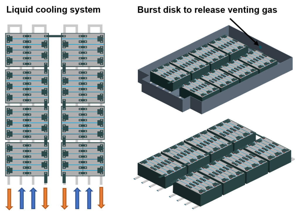
A better strategy is, to slow the spread of thermal runaway between the battery cells down, so that the energy contained in the battery pack is not released at once, but in small amounts for each cell, step by step with enough time in between. In combination with a good battery venting system for efficient gas release and a strong heat resistant battery case, this can minimize the risk and keep the passengers save.
Slowing down the spread of propagation can be realized with thermal insulating materials, specially designed to withstand high temperatures, so called heatshields. We get in contact with a heatshield supplier that suggests us a product that he offers for 3 different thicknesses: 1 mm, 3 mm and 6 mm.
The thickness of the heatshield has a strong impact on the overall size of the battery and and the cooling system in y-direction. To evaluate the best option, we use Simcenter STAR-CCM+ to set up a full parametric battery geometry that scales all parts up or down in dependency of the heat shield thickness:
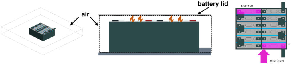
In order to be time efficient, the thermal runaway behavior is analyzed on a single module with surrounding air. The gap between the top of the cells and the lid of the battery casing is modeled accurately to take the reflection of the hot venting gas into account.
We perform 3 thermal runaway simulations for the heatshield thicknesses 1mm, 3 mm and 6mm including venting and analyse the time between the propagations of the single cells. Since our module is parametric, we can set up the thermal runaway model once and use the design study manager in STAR-CCM+ to apply the same model set up for different geometries. Target:
- The requirements for thermal runaway safety depend on the industry sector an cannot be generalized.
- For this fictional scenario it is assumed, that the battery pack is considered as safe if for more than 80% of the cells, the time between the single cell propagations is more than 20 s.
- The areas inside the temperature plots during which the time between the propagation of 2 cells or more is below that value are in the following named as critical areas.
- If a module shows more than 1 critical area during the propagation, it is considered as unsafe.
- In addition, we require a time of at least 15 min between the first cell propagation and the last cell propagation.
- This is just as an example, but as we show a parametric workflow, the requirements can be adapted to the specific case.
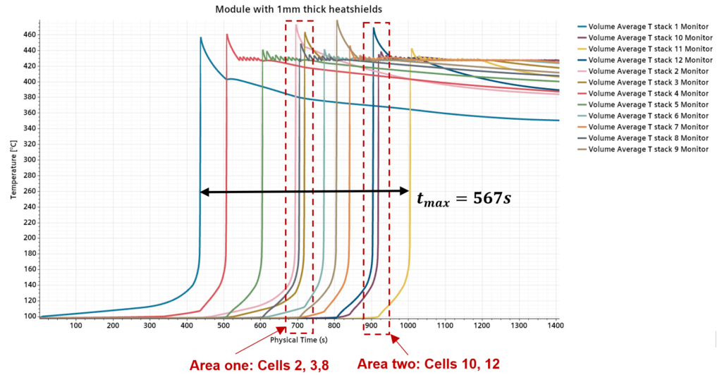

The important information here is the identification of the cells that have too little time between their propagations and the maximum time between the first and the last cell of the module that go into thermal runaway and of course the maximum temperatures. The temperature of the cell lid is also critical to check if it melts of not, but this was not included in this study. For this example, we focus on the propagation speed, a deeper analysis including melting parts due to high temperatures will be shown in other demonstrations.
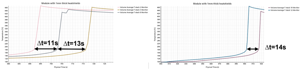
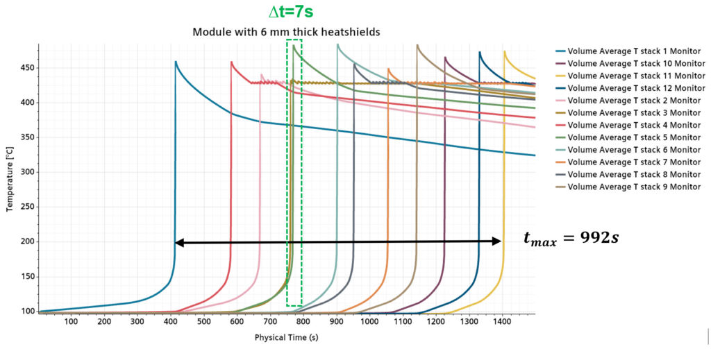
For a battery module with 1 mm heatshield thickness, 2 Critical areas can be identified where the time in between single cell propagations is too short.With a 3 mm heatshield thickness, 3 Critical areas exist with short propagation time deltas between cell pairs. Finally a module with 6 mm heatshield thickness is the safest design! A lot helps a lot! For the set up with 6 mm thick heatshields, there is only one critical area left for which the time difference between two cells is 7 seconds. The rest of the cells propagate with sufficient time in between, leading to the overall longest thermal runaway time, so that the design can be considered as safe!
Part 2: Charge fast and keep cool – Design of the thermal management system
After the thermal runaway safety analysis, the parametric battery gets scaled up according to the heatshield thickness and the design can continue with the thermal management system. As described above, overheating can trigger the cells into thermal runaway and the operation temperature of the battery cells has also a strong impact on their lifetime and performance.
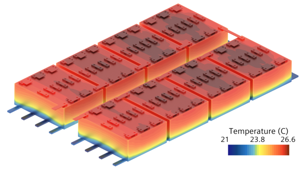
The 3D CFD battery simulation including the cooling system enables the user to identify hot and cold spots early in the design process. This information can later be used to place temperature sensors for experimental tests or to get information about the maximum temperature gradients over the cells, what is important for aging analysis. For the analysis of the liquid cooling system, it is not necessary to simulate the air inside the battery module as it was done for the thermal runaway simulation. It is enough to simulate the cooling fluid and define the heat transfer coefficients between the solid parts and the air inside the battery in form of a convective boundary condition.
The most challenging procedure for the small city bus, like for every electric vehicle, is the fast charging operation. Here, the highest currents occur and the cooling performance is most critical. The bus has the following charging requirements:
| Charging profile | Constant current – constant voltage (CC-CV) |
| Constant current phase | 141 A = charge with 1.5 C |
| Constant voltage phase | 4.2 V per cell |
| Charging time | < 40 min |
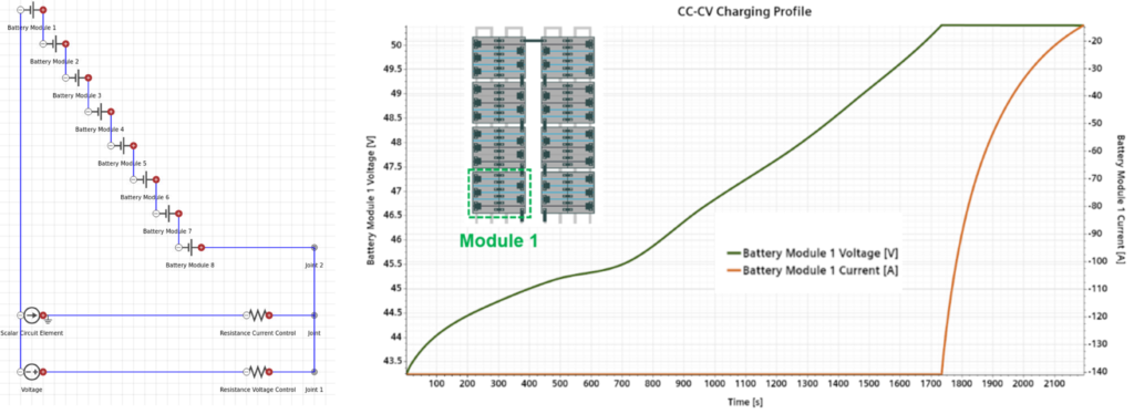
To simulate the electrothermal behavior of the battery, an equivalent circuit model with 2 RC-elements is used. It is part of the user defined battery cell like the Thermal Runaway Heat Release Model that was used for the thermal runaway simulations previously.
Complex electric procedures can be modeled best by using the circuit editor inside Simcenter STAR-CCM+. It contains a toolbox of electric components with which most operations can be realized.
For the constant current constant voltage charging procedure, the following circuit architecture is used:
- Circuit consists of 8 modules in serial connection combined with 2 parallel branches.
- Branch 1: Models the constant current phase of the charging procedure.
- Branch 2: Models the constant voltage phase of the charging procedure.
For the study at hand, the following cooling system parameters are analysed:
| inlet mass flow rate / [kg/s] | inlet temperature [°C] | |
| Battery Simulation 1 | 0.05 | 15 |
| Battery Simulation 2 | 0.05 | 18 |
| Battery Simulation 3 | 0.05 | 21 |
| Battery Simulation 4 | 0.025 | 18 |
| Battery Simulation 5 | 0.075 | 18 |
| Battery Simulation 6 | 0.1 | 18 |
To speed up the calculations, a design sweep operation in the design study manager was used. The six battery simulations can be run in parallel, if Simcenter STAR-CCM+ power on demand licenses are used.
| Mesh size | 14,457,139 cells |
| Hardware used | 4 nodes with 40 CPU cores each |
| Time simulated | 2225 s (~0.6 h) |
| battery simulation runtime | 3.9 h |
From all the analyzed boundary conditions, the combination of a mass flow rate of 0.05 and inlet fluid inlet temperatures of 21°C turned out to show the best results to keep the cells in an optimal temperature range between 24°C and 27°C.
Finally, the design of the battery is completed. The battery has sufficient passive protection in case of a thermal runaway. The fast charging procedure has been modeled to ensure the battery is charged in time and the cooling system parameters have been set to keep all battery cells in the required temperature range.
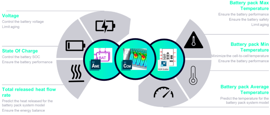
Increasing battery simulation speed while keeping accuracy with reduced order models ROM
For further development of the electric vehicle, it is of interest to predict how the battery interacts with other parts like the environmental control system. Simcenter offers a new type of reduced order model, that combines the high accuracy of 3D battery simulations with the speed of a system simulation. It’s a hybrid between a neural network model for temperature prediction and a system equivalent circuit model:
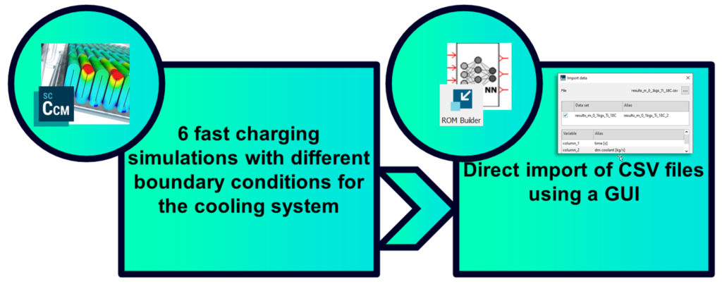
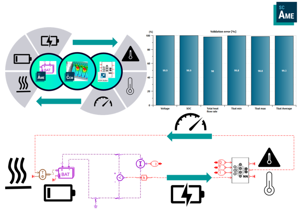
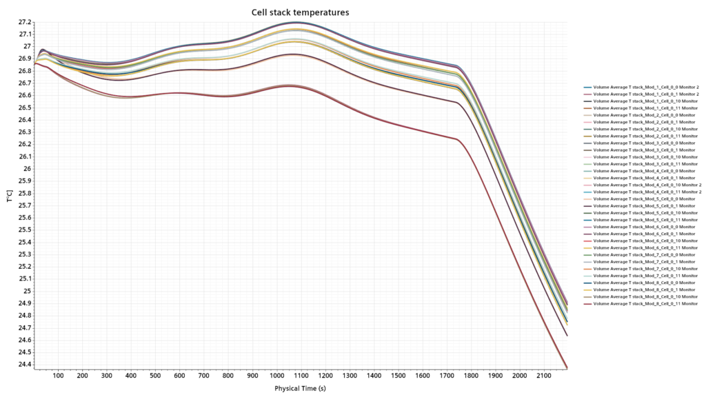
The neural network which has been created with Simcenter ROM builder requires training data to be able to predict the battery cell temperatures. In this case, the six 3D battery simulations that were used to determine the cooling system parameters were given as an input for the training.
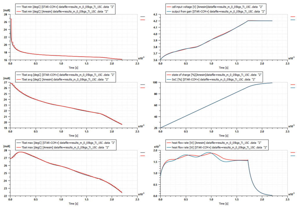
As can be seen in the following plots, the reduced order model predicts the temperatuers of the cell stacks very well and shows nearly the same results as the 3D model. The big advantage here is the required time. While the 3D model requires 3.92 hours for the battery simulation of a 2225 s fast charging cycle, the neural network model is able to do the same in just 0.04s! This enables the usage of the battery model in Software in the loop (SIL) and hardware in the loop (HIL) models and allows the user to integrate it in the overall system model of the battery.
Overcome the trade-off between safety and long range electric vehicles – with Simcenter
Simcenter solutions for battery design enable engineers to increase the electric performance of a battery and hence the range of electric vehicles, while ensuring battery designs that comply with global safety regulations while keeping development cost under control. And so, thanks to a consequent deployment of a digital twin, electric vehicles will never be the big artillery grenades on wheels that “la jamais contente” (“the never happy”) once was.
With the upcoming release of Simcenter STAR-CCM+ 2302 on February 22, the thermal runaway workflow for heat transfer will let you go faster while modeling the complexity. To shorten the waiting time use this last-minute chance and join us for the live Webinar on A multi-physics approach to battery thermal management and runaway analysis