Assess the performance of a hydrogen-powered gas turbine

Compare the performance of a hydrogen-powered turbofan with a kerosene-powered one.
Purpose
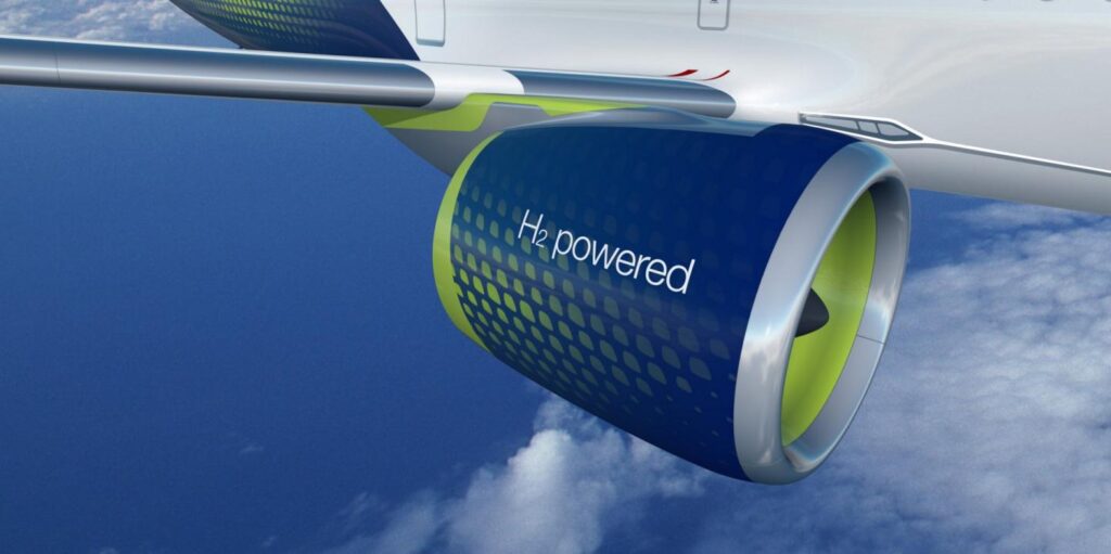
To comply with environmental regulations and reduce fuel and maintenance costs, airframers and engine manufacturers are turning to cleaner gas turbines as alternatives to kerosene-powered ones. These engines use new fuels such as sustainable aviation fuels (SAF), ammonia, natural gas or pure hydrogen. Hydrogen is one of the most promising of them as explained in this article: Hydrogen-powered gas turbines are critical to a low-carbon energy future.
Being able to quickly assess the performance of a hydrogen-powered gas turbine in terms of turbine entry temperature, thrust and fuel consumption and compare with a standard kerosene-powered one is key to unlocking engineering possibilities never seen before.
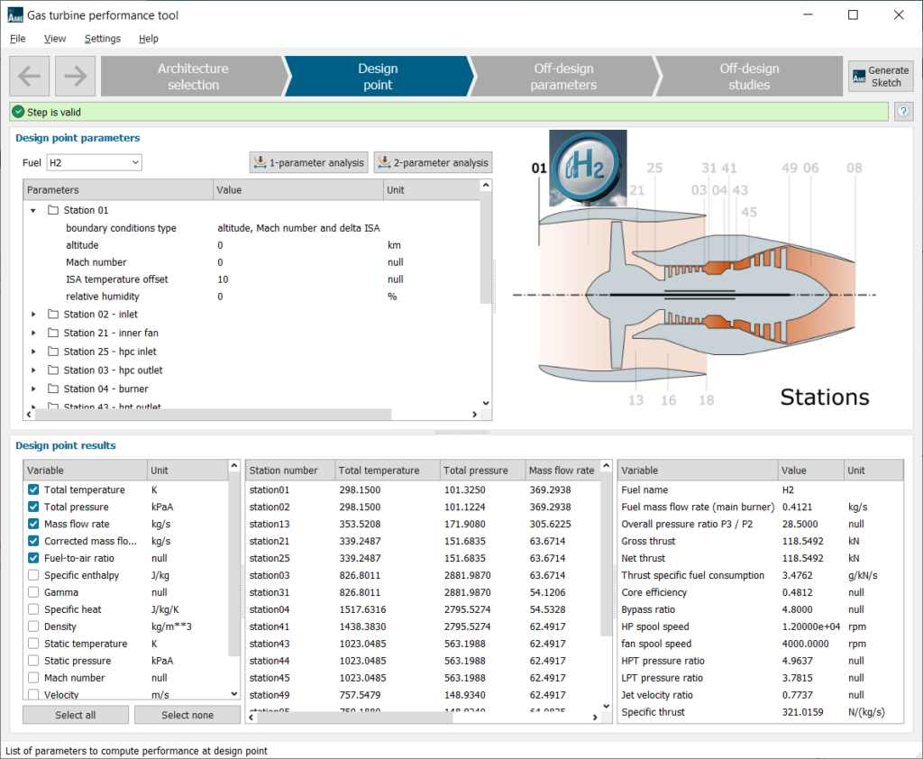
The Simcenter Gas Turbine Performance Tool introduced in Simcenter Amesim 2020.1 is one of the critical pieces of the Siemens Xcelerator portfolio to speed up engine performance calculation. It comes with a set of templates of scalable rubber engine models. These templates can be edited to run fast and efficient pre-design iterations. In this article, we’ll use this gas turbine performance tool to reproduce a study on hydrogen engines done by F. Svensson in his Ph.D. thesis [1].
The engine studied in his paper is the V2527-A5, manufactured by IAE. It is an unmixed-flow boosted turbofan composed of a single-stage fan, a four-stage low pressure compressor (LPC) and a ten-stage high pressure compressor (HPC). The HP and LP turbines are respectively composed of two and five stages.
The design point parameters are listed below:
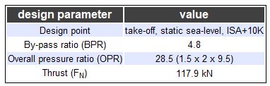
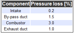
The assumed component efficiencies and pressure ratios, as well as the losses are presented in the next two tables.
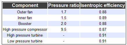
Remark: In the gas turbine performance app, the booster and high-pressure compressor are grouped into a single component, an isentropic efficiency of 0.87 was assumed for it.
The following assumptions are made to model the engine cooling flows:
- 15% of the core air is bled off after the HPC
- To simulate nozzle guide vane (NGV) cooling, 12.5% of the bleed is injected upstream of the HP turbine, and the remaining 2.5% is injected upstream of the LP turbine.
A single-parameter study on the inlet corrected mass flow rate at station 2 is performed in order to fit the inlet mass flow rate provided in the thesis.
The nozzle thrust coefficient is set to 0.98 as specified in the paper.
Similarly, burner parameters like the combustor outlet temperature (COT) and the kerosene lower heating value (LHV) are respectively set to 1555 K and 43.124 MJ/kg as proposed by the author.
Performance models of the three cycles are stored in the model’s folder named ‘HydrogenPoweredTurbofan_.datafiles’ and can be open with the Simcenter Gas Turbine Performance Tool.
Kerosene-powered engine performance
The performance obtained in the gas turbine performance tool is compared with the author results in the table below.
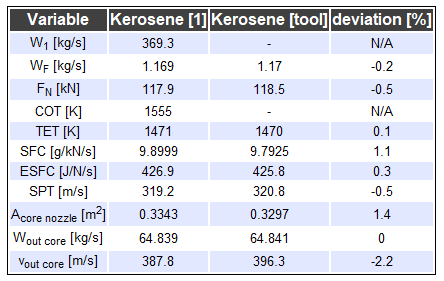
We can notice that all of the results show a very good agreement with those from the literature.
We can derive two hydrogen-powered alternatives from this model as proposed in the reference study. In the first one, we keep the same COT (Combustor Outlet Temperature); in the second one, we set the model parameters to reach the same net thrust.
H2 equivalent COT performance model
Setting up the first engine derivative is very straightforward. Without changing the burner temperature, we just select H2 as fuel and change the fuel lower heating value to 120 MJ/kg. The tool automatically recomputes all the engine performance data.
It leads to the following results, showing again a very good agreement with the literature.
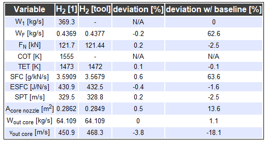
In the hydrogen-powered cycle, we notice a significant drop in fuel consumption by almost 63% and, therefore, a similar gain in the specific fuel consumption. The net thrust shows a slight increase of 2.5%, just like the energy-specific fuel consumption and the specific thrust. It is interesting to note that the core flow is not really impacted, while the flow speed at the core outlet is vastly increased, and a reduced flowing area of the core nozzle should be considered.
H2 equivalent FN performance model
In order to set up a hydrogen-derivative with a thrust equal to the kerosene engine, we perform a single-parameter study with a variation of the burner exit temperature to find the combustor temperature that will result in a net thrust of 118.5 kN.
With a burner temperature of 1517.6 K applied to the H2-cycle, we get the following performance results.
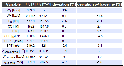
Again, a good agreement is shown when we compare with the paper. Regarding the deviation from the baseline and the equivalent-COT variant, we can note slightly higher benefits in fuel consumption and specific fuel consumption and a decrease in the combustor outlet temperature by around 30 to 40 [K].
Conclusion
This demo showed the value of simulation in addressing the challenges posed by clean aviation. The Simcenter Gas Turbine Performance Tool offers cycle calculation capabilities that allows you to evaluate on-design performance for new types of fuel never used before in commercial aviation. From the cycle performance model, it is also possible to generate automatically a transient Simcenter Amesim model of the hydrogen-powered engine as shown here and make further changes to it, to explore other design choices like adding a closed-loop recuperated cycle. The multiphysics system integration capability of Simcenter Amesim makes it possible to even connect this engine model to a flight performance model of the aircraft as shown here to see how the aircraft total weight increase (because of the LH2 tanks) and the resulting aerodynamics will impact range and fuel consumption. Other engineering challenges posed by hydrogen-powered aircraft are related to liquid hydrogen (LH2) cryogenic storage and distribution, Simcenter Amesim offers modeling capabilities to address these challenges as well.
About the author:
Djiby Touré is an advanced application specialist for Simcenter Systems with the Aerospace and Defense product management team. His work focuses on electrical systems, clean propulsion and its impact on flight performance.
Glossary
- W1 [kg/s], air mass flow rate at station 1
- WF [kg/s], fuel mass flow rate injected in the combustor
- FN [kN], thrust
- LHV [MJ/kg], Low Heating Value of the fuel
- COT [K], Combustor Outlet Temperature
- TET [K], Turbine Entry Temperature
- SFC [g/kN/s], Specific Fuel Comsumption computed as the mass flow rate of fuel divided by the thrust
- ESFC [J/N/s], Energy Specific Fuel Consumption being the LHV times the SFC
- SPT [m/s], Specific Power Thrust computed as the air mass flow rate divided by the thrust
- Acore nozzle [m2], cross section area of the core nozzle – station 8
- Wout core [kg/s], mass flow rate at the outlet of the core nozzle – station 8
- vout core [m/s], flow speed at the outlet of the core nozzle – station 8
Going further
- [1] Svensson, F. (2005). Potential of reducing the environmental impact of civil subsonic aviation by using liquid hydrogen (Doctoral dissertation, Cranfield University)
- Blog post “Hydrogen-powered gas turbines are key to a low-carbon energy future“
- On-demand webinar “Assessing thermo-electric powerplants for rotorcraft using system simulation“
- On demand webinar “Jet engine and gas turbine system simulation“