Using system simulation to evaluate the integration of a Solid Oxide Fuel Cell (SOFC) with a methane reformer to power a cargo ship.
Introduction
In today’s global race for energy decarbonization considering a net-zero target in 2050, mobility is facing the challenge of finding achievable and cost-effective solutions. All transportation modes are concerned. According to the International Maritime Organization, international shipping is responsible for approximately 2-3% of global CO2 emissions.
Solid Oxide Fuel Cells (SOFCs) and Natural Gas or methane (CH4) reformers can be used in ships to provide an efficient and clean power generation system. It comes with challenges, including cost considerations, infrastructure requirements, and technological advancements. As technology continues to evolve, these challenges may be addressed, making fuel cell systems more viable for marine applications and using a Solid Oxide Fuel Cell with a CH4 reformer in a ship could generate significant benefits:
- SOFCs are known for their high efficiency in converting fuel to electricity. They can achieve efficiencies of up to 60%, which is significantly higher than traditional combustion engines.
- SOFCs produce electricity through an electrochemical process, which is inherently cleaner than combustion-based power generation. This results in lower emissions of pollutants such as NOx, SOx, and particulate matter.
- When coupled with a CH4 reformer, which produces hydrogen from methane, SOFCs can run on hydrogen, a clean fuel that generates only water vapor as a by-product when used in the fuel cell. This helps in reducing greenhouse gas emissions compared to traditional fossil fuel-based systems.
- SOFCs can operate on a variety of fuels, including hydrogen, methanol, natural gas, and other hydrocarbons. The use of a CH4 reformer allows for the extraction of hydrogen from methane, providing fuel flexibility and adaptability to different fuel sources.
- Fuel cells operate silently compared to traditional engines, contributing to a quieter and more comfortable environment on the ship. This is particularly important for passenger ships and naval vessels where noise reduction is a priority.
- SOFCs have fewer moving parts compared to traditional engines, resulting in lower maintenance requirements and longer operational lifetimes. This could lead to cost savings over the lifespan of the system.
- SOFCs can be configured for cogeneration, simultaneously producing electricity and heat. A microgas turbine can eventually be connected to such a system as well. The waste heat generated during the electrochemical process can be utilized for various onboard applications, such as heating and water desalination. It can also be used to warm up the CH4 reformers that consume heat to generate hydrogen. In this configuration, the system’s efficiency can easily reach 90%
- The high energy density and efficiency of SOFCs can contribute to longer ranges and extended endurance for ships, making them suitable for long-distance voyages without frequent refueling.
A model of a cargo ship powered by a SOFC combined with a CH4 reformer has been built using the system simulation tool Simcenter Amesim. Thanks to this model, it is possible to simulate the behavior of the ship and its powertrain system considering different sea routes and sea conditions. It helps for instance to evaluate the fuel consumption of the ship, and the amount of CO2 that will be generated by the ship. It can also be used to predict and better understand the interactions between the components of the system. Finally, simulations can be used to evaluate design options that can help to reduce energy consumption and CO2 emissions.
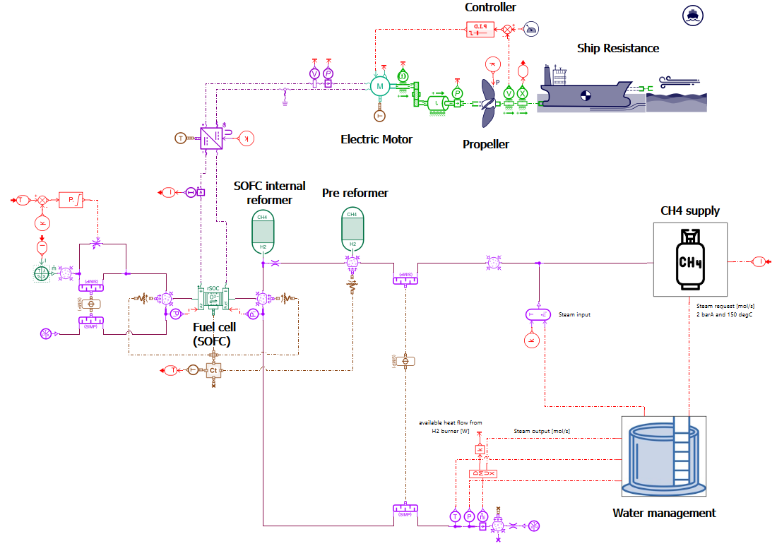
Model presentation
Sea conditions and ship resistance
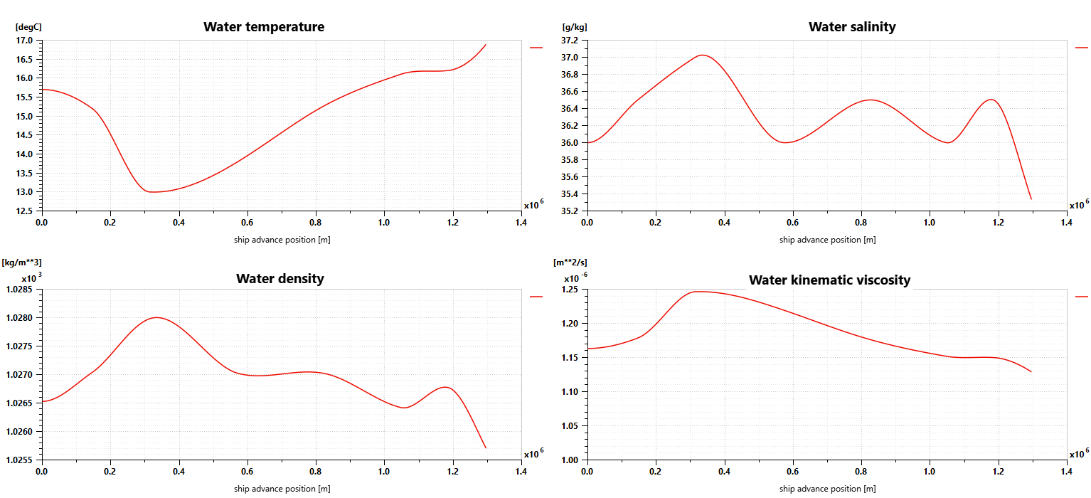
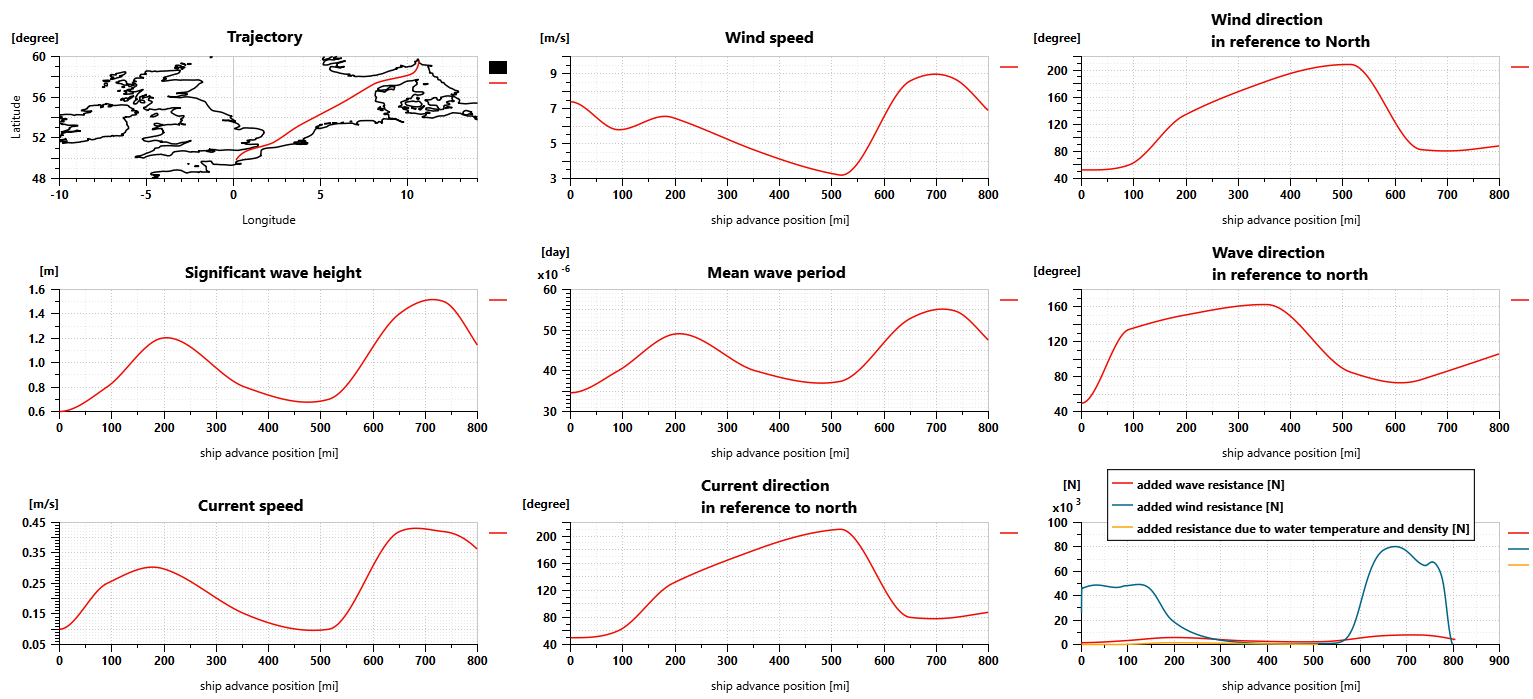
Using Simcenter Amesim makes it possible to define the sailing conditions, including the sea route based on GPS positions but also variable water salinity and temperature, wind speed and direction, wave height and period, and water current speed and direction.
For our simulations, the sea route is defined according to a trip from Oslo (Norway) to Le Havre (France). Sailing conditions are defined as shown in the picture below. The ship weighs 8000 tons, is 75 meters long and 9 meters wide, and requires almost 4 days to perform the trip.
The Simcenter Amesim ship model predicts the longitudinal motion of the ship, considering its mass and the navigation resistance due to friction. This takes into account the water variable density and viscosity, wind and waves.
Propeller
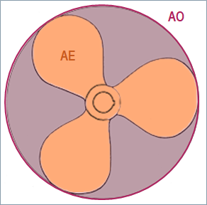
The propeller model is used to compute the thrust and the torque. During our simulations, we selected the Wageningen B-series propeller model proposed by Simcenter Amesim using as inputs the propeller diameter (6 m), the blade area ratio AE/AO (0.57 – AE: propeller expanded blade area, AO: Propeller disk area) and the number of blades (4). The propeller pitch is assumed to be constant (3.5 m).

Propeller model
Electric motor and its transmission
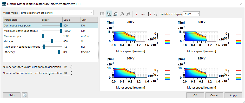
The propeller is powered by a 1.2 MW electric motor. Its maximum continuous torque is 15000N.m. Its efficiency is set to 90%. The Simcenter Amesim electric motor model is a tabulated one. An embedded tool, the Electric Motor Tables Creator can be used to automatically generate the model maps from a few input data.

A PID controller is used to define the motor torque request with the purpose of getting the best match between the ship velocity and the target velocity.
A DC/DC converter integrated between the Solid Oxide Fuel Cell and the motor maintains the motor voltage at 800 V.
A transmission with a ratio set to 12 is integrated between the propeller and the motor to adapt the velocity and the torque between the 2 subsystems.
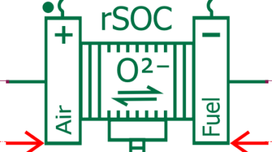
Solid Oxide Fuel Cell (SOFC)
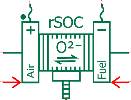
The Solid Oxide Fuel Cell (SOFC) is an electrochemical device that generates electricity by utilizing the electrochemical reaction between oxygen from the air and a fuel, typically hydrogen or natural gas. Unlike traditional fuel cells, SOFCs operate at high temperatures (typically between 500 to 1000°C), allowing for efficient conversion of a wide range of fuels into electricity. They are known for their high efficiency, low emissions, and versatility in fuel sources, making them suitable for various applications, including power generation and marine transportation.
In our electrochemical model, hydrogen is extracted from CH4 using a reforming process (with an external pre-reformer and internal reforming occurring inside the fuel cell). Consequently, the SOFC anode is supplied with a mixture of gas including H2, but also CH4, CO, CO2, and H2O (as vapor).
The Simcenter Amesim Solid Oxide Fuel Cell model predicts the fuel cell voltage using the Butler Volmer electrochemical equations, considering the activation, ohmic, and concentration losses. It captures the impact of operating conditions such as the temperature, pressure, and reactant concentration. Moreover, as carbon monoxide is present in the fuel, it can also undergo electrochemical oxidation at the anode, contributing to the overall cell reaction.
The fuel cell heat losses are predicted considering the thermoneutral potential, making it possible to evaluate the transient thermal behavior of the SOFC.
In our model, the SOFC is made of 1500 cells with an active area of 1000cm2 for each of them. It is sized to deliver an electric power of up to 1.2 MW. Note that we consider here an equivalent global stack, which would be most likely made of 4 individual 300kW stacks in the actual set-up.
Note: The Simcenter Amesim Solid Oxide Fuel Cell model can be used to simulate a Solid Oxide Electrolyzer as well and the same subsystem is capable of performing the reversible reactions.
CH4 reformer
The CH₄ reformer is used in our system to produce hydrogen from methane. It operates primarily through a process called Steam Methane Reforming (SMR).
Methane and steam (H₂O) are fed into a reformer chamber. The steam-to-carbon ratio (ratio of moles of steam to moles of methane) is a key parameter for the reaction’s efficiency and is typically between 1:1 to 3:1. In our model, the steam-to-carbon ratio is set to 2.5:1.
Inside the reformer chamber, the methane and steam are heated and passed over a catalyst bed, usually containing nickel. This catalyst facilitates the reaction, especially at lower temperatures. The primary chemical reactions involved are:
CH4 + H2O <-> CO + 3H2
CH4 + 2H2O <-> CO2 + 4H2
These reactions are endothermic, meaning they require heat. The methane and steam mixture is heated to high temperatures (typically between 700°C and 1,000°C) to drive these reactions.
Along with hydrogen production, carbon monoxide (CO) is also formed as a by-product of the reaction. The presence of CO is undesirable in many applications due to its toxicity and potential to poison catalysts. Therefore, additional steps are usually employed to shift the equilibrium towards more hydrogen production and less CO. In our model, a water-gas shift moderately exothermic reaction is also considered:
CO + H2O <-> CO2 + H2
As the reforming reactions are globally endothermic (meaning they absorb heat), to maintain the required reaction temperatures, heat is typically supplied to the reformer, either through external heaters or by combusting a portion of the produced hydrogen or methane. In the Simcenter Amesim CH4 reformer model, it is possible to actuate the methane combustion reaction to simulate an auto-thermal reaction. However, in our ship model, we prefer considering that the reformer is using the heat losses of the SOFC to maintain its temperature in the required range.
In our model, to maximize efficiency, and overall system performance, we combine 2 reformer reactors. The 1st one, external to the SOFC, extracts the largest quantity of H2 from the CH4. Then, an internal reformer integrated with the SOFC anode can further refine the fuel stream to maximize hydrogen content and consume almost completely methane.
Reformer CH4 and steam supply
The quantity of methane that must be supplied to the reformer depends on the quantity of hydrogen that must be provided to the SOFC to perform the electrochemical reactions. In our model, the methane flow rate feeding the reformer is defined from the electrical current delivered by the fuel cell considering a targeted Fuel Utilization of 75%.
The steam flow rate delivered to the reformer is calculated from the methane flow rate and the steam-to-carbon ratio.
The mixture of methane and steam is supposed to be at 150°C before it comes to a heat exchanger used to extract heat from the gas mixture leaving the SOFC anode. In that way, the methane and steam mixture are pre-heated before reaching the reformer, improving the global efficiency of the reformer.
Air supply
As for methane and steam, the quantity of air that is delivered to the system, at the SOFC cathode side, is predicted from the electric current delivered by the fuel cell, based on a stoichiometric ratio of 1.5 for the oxygen.
Still, to reduce heat losses and improve the global system efficiency, a heat exchanger is integrated into the air supply system to warm up the airflow before it is supplied to the SOFC cathode. That can be done by extracting heat from the airflow coming from the cathode outlet. However, in some conditions, especially for high power demands, the system temperature could exceed the expected maximum value set to 950°C. To avoid such a situation, a bypass system with a controlled valve is integrated. That makes it possible to reduce the fuel cell temperature by supplying fresh air instead of warm air to the SOFC.
Water management
As discussed previously, we defined our system architecture to extract heat from some components and deliver it to others with the goal of improving the system’s overall efficiency. Another point of interest is the water management.
Indeed, on one side, the reformer is consuming water with its steam reforming reaction. And at the other side, the SOFC electrochemical reactions are producing water.
So, to make the system autonomous regarding water, it is possible to recover the water that is rejected at the SOFC outlet, to store it and use it to supply the reformer reactor.
Simulation and analyses
Global results
Simulating the 4-day trip from Oslo to Le Havre is very quick (a few seconds on a basic laptop). That would make it very easy to perform many simulations to evaluate different scenarios or several design options.
Regarding our case, we can first validate that the powertrain and its control make it possible to sail at the expected velocity.
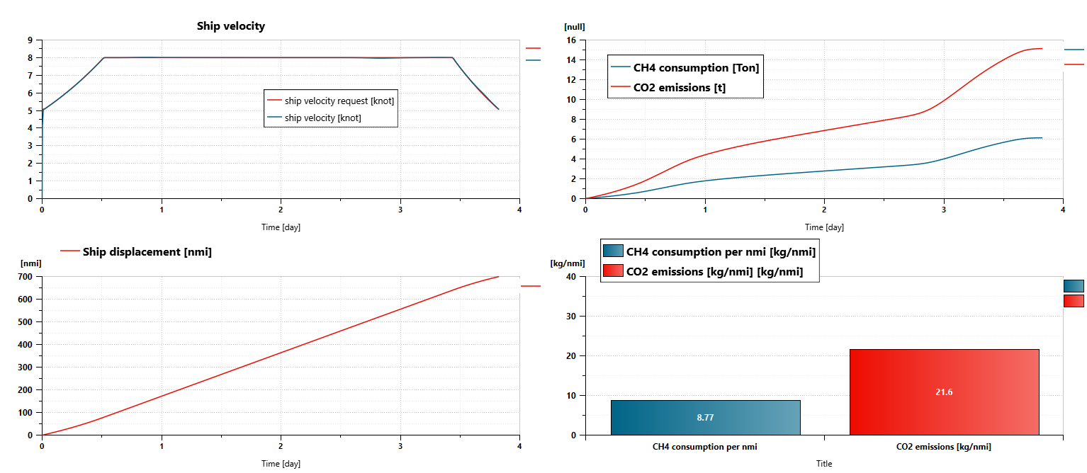
We can also easily get the following results at the end of the simulation:
- Trip distance: 700 nmi
- Trip duration: 330564 s (3 days, 19 hours, 49 minutes and 24 seconds)
- CH4 consumption: 6.13 t
- CH4 consumption per nautical mile: 8.77 kg/nmi
- CO2 emissions: 15.1 t
- CO2 emissions per nautical mile: 21.6 kg/nmi
- Global system efficiency (from CH4 tank to propeller, based on CH4 HHV): 42%
External reformer
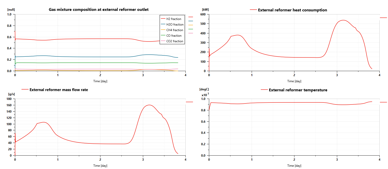
The ship model can predict the external reformer’s average temperature, pressure, heat balance, and mass flow rates. They are evolving dynamically during the trip, depending on the quantity of hydrogen that needs to be produced by the SOFC.
The endothermic chemical reactions require up to 540 kW of heat. The gas mixture temperature, inside the reactor remains between 700°C and 920°C, enabling the chemical reactions to occur properly.
Simulations can also predict the gas mixture composition at the outlet of the gas chamber. We can hence check that:
- We deliver excess water to the reactor all along the trip: the vapor concentration remains close to 25%.
- The most important part of methane is consumed to produce hydrogen. CH4 concentration remains between 1% and 3%.
- The gas mixture is mainly made of hydrogen with a composition usually between 53% and 56%
- CO and CO2 are the by-products of the reaction with a concentration of CO that can reach more than 14%.
Solid Oxide Fuel Cell (SOFC)
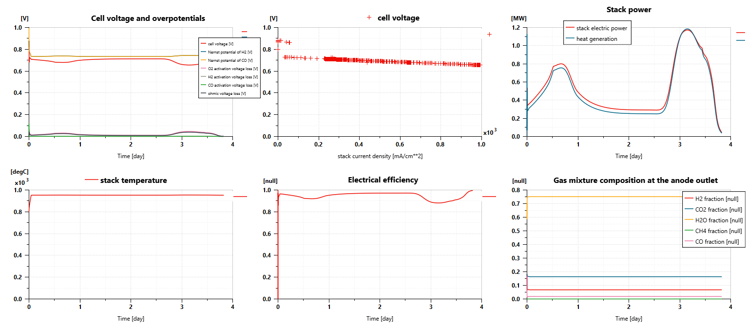
The cell voltage remains generally close to 0.7V. It is predicted from the Nernst potential of the reactions with H2 and CO and the voltage drops due to activation and ohmic losses. The operating Nernst potentials are quite low compared to Nernst potentials in standard conditions as it is impacted by the high temperature of the SOFC. Regarding activation losses, the ones related to O2 are the predominant ones.
The electric power delivered by the stack can reach almost 1.2 MW. The heat generated by the losses has the same order of magnitude. In that context, the SOFC thermodynamic efficiency remains slightly above 50%.
The fuel cell temperature remains close to 950°C.
Due to the fuel cell reactions and the internal reforming process, the content of methane is close to 0% at the anode outlet when the gas mixture still contains some excess hydrogen (around 7%). The content of CO is close to 2%. An additional reactor could be required to reduce this one. The concentration of CO2 is close to 16% and water vapor concentration is close to 75%.
At the cathode side, air is also supplied with excess. The concentration of oxygen at the outlet is close to 8%.
Heat exchanges and thermal management
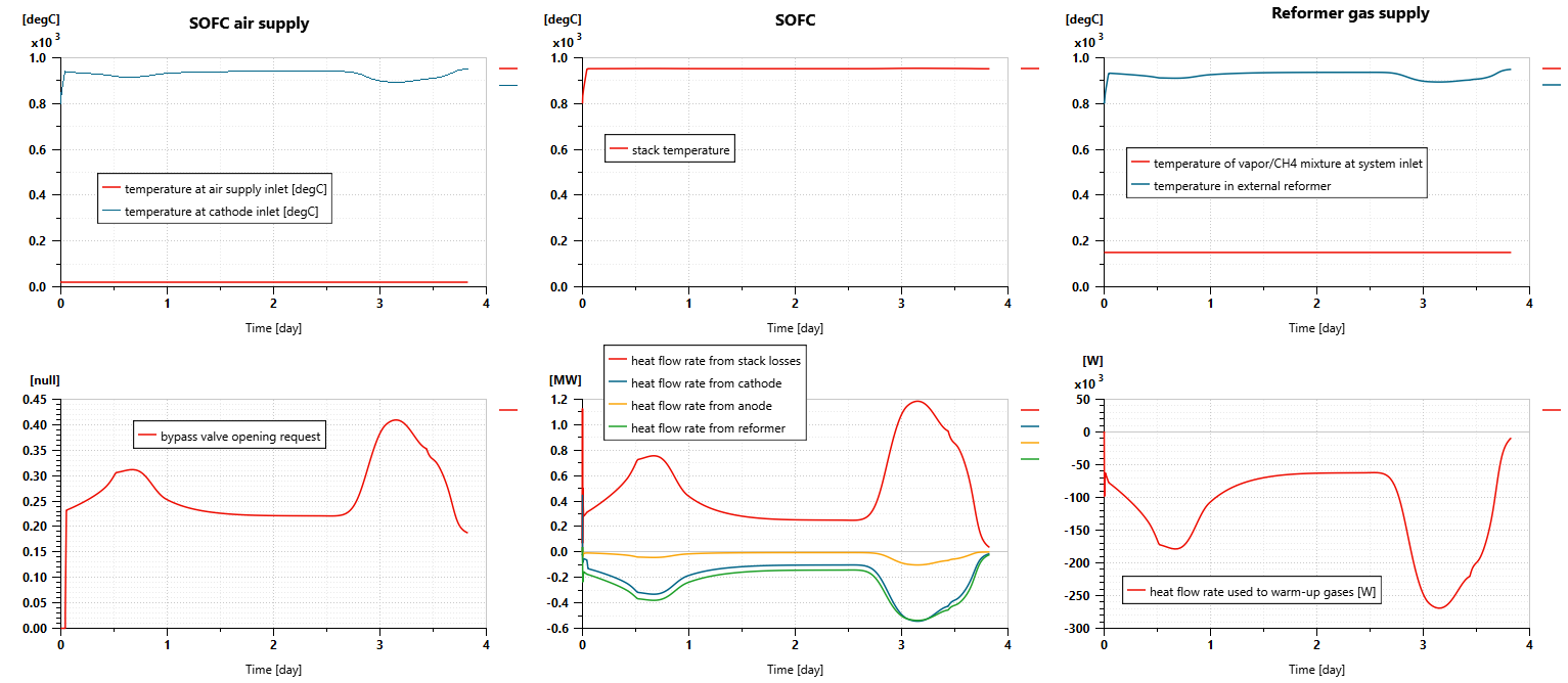
Our system model can help to better understand heat flow rates, heat exchanges and thermal transients in the fuel cell system. This is indeed crucial to maintain the SOFC and the reformer at the right range of temperature to operate efficiently. The energy losses can also be potentially recovered to improve the overall system efficiency.
As shown in the next picture, the heat exchanger between the airflow going to the fuel cell (initially at ambient temperature) and the airflow exiting the fuel cell (at a temperature close to the stack one) helps to supply warm gases to the SOFC (at a temperature above 900°C). We can also notice that the bypass valve is actuated to control the SOFC temperature and maintain it to a temperature below or close to 950°C.
As for the air, the mixture of steam and methane is warmed up before feeding the reformer, extracting some heat from the gas flow exiting the fuel cell anode. In that way, the gas mixture can reach the reactor at a temperature close to 900°C.
Using the Simcenter Amesim Sketch Animation is also very interesting for quick visualization of the temperature evolution in the different parts of the system.
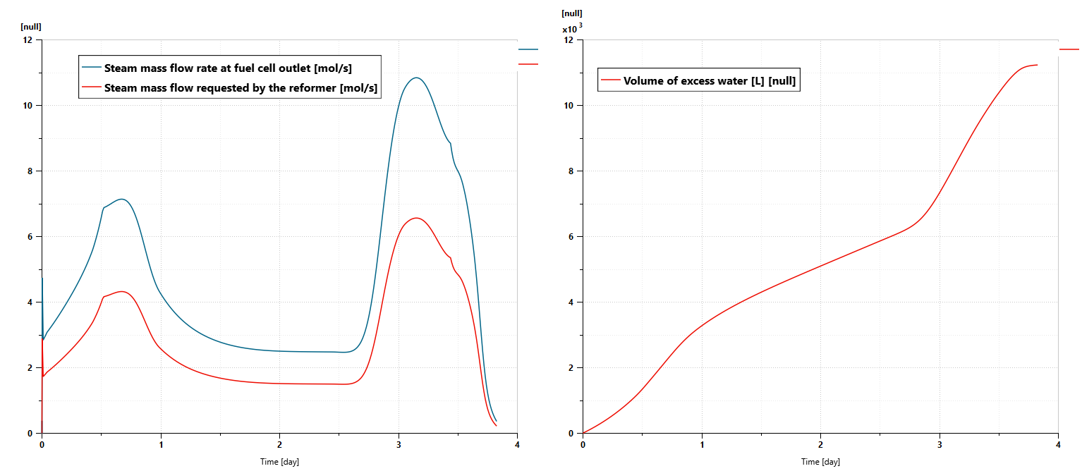
Water consumption and production
The quantity of water supplied to the reformer and the content of water in the gas mixture leaving the SOFC are evaluated during the simulation. As shown in the next picture, the quantity of water that is supplied to the reformer is always below the quantity of steam that can be retrieved at the SOFC outlet. That means that the system does not need any external water supply. It is possible to recover water from the SOFC, for instance after condensation, and use this water to feed the reformer. Some excess water could even be used for other usages, for instance, the generation of drinkable water, for the ship bathroom…
Conclusions
Thanks to Simcenter Amesim, we have been able to model a cargo ship powered by a Solid Oxide Fuel Cell combined with a CH4 reformer. With such a model, we have been able to capture not only the behavior of the different subsystems but also the way they interact with each other. This enables us to validate the concepts, subsystems sizing, components thermal management and to predict the performance, fuel consumption, and CO2 emissions of such a powertrain solution.
As simulations can be performed very quickly, the model can be used to assess other design variants as well as many scenarios regarding the sea route or the sailing conditions.
In the next step, Simcenter Amesim also makes it possible to add more physics in the model to improve the simulation level of accuracy but also to design with more details the ship subsystems such as the SOFC balance of the plant, the thermal management (including pumps, geometry-based heat exchangers…)
Additional components such as a burner used to burn the excess of hydrogen that exits the SOFC anode can also be integrated. The heat that can be generated by this combustion could be valorized to further improve the efficiency of the system.
Regarding controls for components such as valves, pumps, and compressors, more detailed strategies can be assessed using Simcenter Amesim. A coupling between the model of the physical system and Programmable Logic Controllers (PLCs) could also be used during project pre-commissioning.