Serving a perfect Stout – the CFD way
This blog is dedicated to Stephen McIllwain, one of the greatest Irishman and managers I know.
St. Patrick’s day is back to normal! Pubs around the globe are back up open, waiting for the thirsty crowd to come in and have a pint. And I? Well, now admittedly, as I am German, you would probably expect me to talk about Weissbier and Biergarden I assume, about German beer traditions, the price of the Maß at Octoberfest and how we Germans have invented the Reinheitsgebot. Well, I leave that to others. Instead, I admit it – in the hope, my Bavarian mates won’t read this – I also do love a stout here and there. And I am a big fan of St. Patrick’s Day.
Now combine stout with Computational Fluid Dynamics and you can have a drink in the home office, fully compliant, thanks to a comprehensive digital twin!
But enough talking, time to pour!
The perfect pour
As a fluid mechanics engineer, I thought I’d pour you a perfect stout in a yet unseen way. The first step to do so: research what a perfect pour requires, and that recipe to perfection is this:
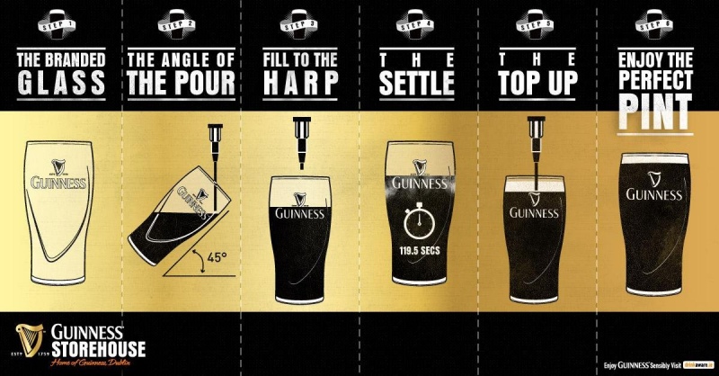
The perfect stout – delivered by a CFD tool?
The question to me was: Can I replicate this pour to perfection within a CFD simulation tool? With incorporating all the physics that matter to a proper stout (and believe me foam could be a nightmare). With all the steps the bartender goes through to craft a perfect beer. With all the moves it requires. Without writing a single line of code. With outputting a result that will make you want to drink a pint the moment you see the animation. And – beyond all that – with generating insights into the magic that happens insight a glass of stout that only CFD simulation can reveal. And all that without any manual intervention, once I’ve told the software what it has to do.
Here’s the first ever stout served in perfection – by a CFD simulation tool.
1. Start from a clean glass
In CFD simulation and real life it starts with a clean glass. Clean in the CAE world means, you need to ensure you have error-free CAD data of the glass and a high quality computational grid theeafter.
With the right CFD tool you can easily identify errors in CAD and fix those. Or even design your own glass.
Clean watertight geometry is a precondition to generating a high-quality computational grid. Only if your glass is clean and appropriately shaped will you observe the signature foam crown forming in real life and CFD. (For the latter you might otherwise end up with a crashing simulation). Now I am a lucky chap to hold a tool to do all this in my hands.
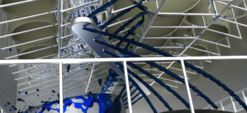
2. The 45 degree angle pour
The right motion is everything. Stout masters tell us we have to pour in the beer in two steps. During the first filling interval you need to start with the glass under the faucet in a 45 degree angle and (for a branded glass) target the harp at roundabout 3/4 of the overall height.
For a CFD engineer this means you need to make some transformations to the geometry to place it at the correct place and in the correct inclination. Not a big deal with embedded transformation operations.
Then you start the filling process.
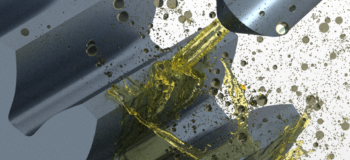
Modeling stout
In CFD you need to describe stout at least as a two component fluid. There is the liquid beer and there is the tiny nitrogen bubbles that give it the signature foam crown after the settling process. I use a Eulerian multiphase modeling approach to describe these phases with a volume of fluid description for the beer. While this is obvious for the liquid beer, for the bubbles a continuous modeling approach is not immediately obvious. At first sight for bubbles a Lagrangian approach seemed to be a natural choice but I decided to go for continuous Eulerian description here – modeling the bubbles as Nitrogen gas with the density of typical beer foam.
Now clearly this is an approximation. However, there are millions of those bubbles in reality and they interact very non-linearly especially as they adhere to one another and form the foam crown. As these transitional physics scared me a bit I thought I’d start a little simpler. So I felt more comfortable to model the bubbles as a continuum in first place. The remaining third phase involved in the multi-phase approach is the surrounding air.
In order to describe the free surface of beer versus the surrounding background air precisely at minimal computational cost I am leveraging model driven adaptive mesh refinement. The latter automatically refines the mesh at the interface between air and liquid as the pouring progresses.
3. The 3/4 fill
When the bartender opens the valve and let’s the beer flow into the glass he starts off in 45 degrees. The target of this first filling sequence is a three-quater fill of the glass, which typically takes roundabout 8 to 10 seconds. However, if you watch the real experts closely as they reach roundabout two thirds they already start to increase the glasses inclination angle toward the final vertical orientation.
In CFD this movement requires the description and modeling of body motion. As the glass moves the computational grid of the glass moves along with it, while the static mesh that contains the faucet and it’s surrounding remains in a static position.
Overset meshing is the ideal candidate to impose any required motion to the glass, mimicking the bartenders handling with excellent mesh quality throughout the process. To further increase fidelity and stability I am one more time using the adaptive mesh refinement capabilities, this time to refine the overset mesh interface between the moving and the static background grid.
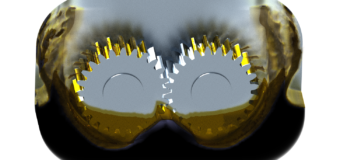
4. The settle
Now comes the hard but at the same time most exciting part! Waiting! And staring!
Thirsty and in expectation of the first explosive and refreshing sip, both beer lovers and CFD engineers now sit there and watch the millions of bubbles travel their unusual way through the glas. You can find dozens of (semi)scientific studies on the popular phenomenom that the bubbles of the Guiness foam seem to travel downwards, while they cumulate at the top as the beers settles in a mesmerizing process going through a beautiful color transformation.
What happens? What’s the magic?
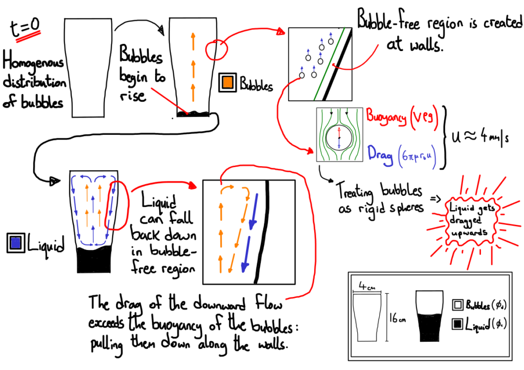
As a matter of fact, the bubbles indeed travel downwards on the outer side of the beer, visualizing the downward facing current in the outer beer regions towards the glass. What the observer does not see is there is a counteracting upward facing flow in the center of the glass: The latter is caused by Nitrogen bubbles rising from the bottom in center of the glass due to their lower specific weight. That current becomes so strong that it sucks bubbles from the outer glass towards the center and ultimately forcing bubbles in the outer beer to go downwards, then mid-wards before they rise to the top and form the legendary white crown. What forms – in a nutshell- is a donut shaped flow.
This flow is kept upright until almost all Nitrogen bubbles have reached the top and formed a cohesive foam layer on top of the dark liquid beer underneath. In reality the whole process takes roundabout a minute.
It turns out that my current multiphase modeling approach seems to be underestimating the de-mixing timescales. In the CFD when the pour stops a big portion of the settling has already happened. As a consequence the donut-shaped flow could not be seen as it’s overlaid by the filling and it does not significantly evolve during the settling process as barely any driving gas dissolved in the beer is left. Anyways, at the end at least all foam is atop of the beer. But clearly for my CFD bartender career, I will deepen my research homework, refine the modeling and continue practicing that part.
Luckily, my CFD offers automatic adaptive time stepping so that even a span of two minutes can be simulated before dehydrating.
5. The top up
Once the settling is accomplished it’s time for the bartender to add the second fill aka the top up. This final fill that generates the ultimate beauty of a stout pint. Now the glass is in vertical position and the filling rate is throttled such that their is another gentle stir-up up the beer until the final foam crown forms slightly sticking out of the glasses top.
For the sequence of opening and closing the nozzle, adjusting the flow rates, setting the respective timings of each sub-process, triggering the glass motion etc. I am using Simulation operations. The latter are an embedded functionality to drive complex simulation processes without any scripting or manual intervention. Apart from setting parameters and driving the numerical solver, those include logical events, loops and other useful programming fundamentals to bring a simulation process to life.
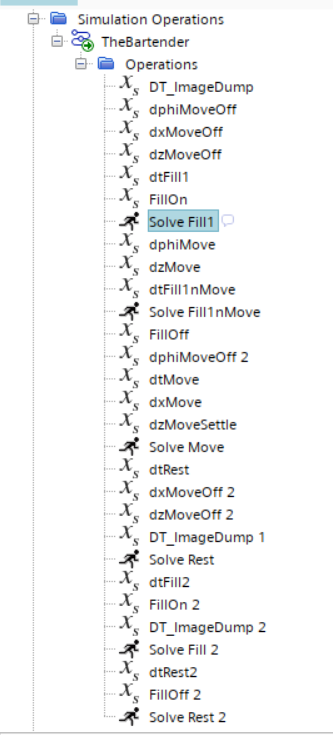
I called my Simulation Operation “The bartender” because it knows all the tricks to serve a perfect stout.
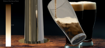
6. The presentation
Finally! It’s here in all it’s perfection, beautiful to look at. And ready to drink.
To honor this perfection in a CFD environment it requires high quality rendering capabilities. And – just like for the real beer – it requires care and the desire for perfection. I think engineers and bartenders at this point are no different: I cleaned the glass, I polished the fountain, I carefully watched the colors of foam and beer.
I wanted to honor a craft and a legendary beverage with the most beautiful postprocessing it has ever seen.
But all this is worthless without a decent validation experiment. So I hope you now want a stout as desperately as I want. For scientific reasons of course. And, for the CFD engineers among you, if you want to know more about the first CFD software that has become a decent bartender and crafted the perfect digital twin of a stout. Check out more on Simcenter STAR-CCM+ multiphase capabilities. And even more in the Related blogs below.
Validation time. Cheers, mates!
With that being said, time to validate the world’s first virtual stout crafted by a CFD tool.
Happy St. Patrick’s day, all. Cheers!
And don’t you please tell my Bavarian friends about this blog 😉
Comments
Comments are closed.
Nice blog! Does your bartender also serves wine? I come from baden-Württemberg 🙂