5 Steps to prepare CAD for CFD Simulation…The Easy Way!
“If you want to go far, go together. If you want to go fast, go alone!”
At some point, we all find ourselves at the same crossroads – go far, or fast? Most of the time, simulation engineers need to go far, but also fast.
If only it were that simple. Historically, going from CAD to mesh (in other words, laying the foundations for a single simulation) has been the biggest bottleneck in the simulation process, consuming up to 50% of the engineering budget. The time consuming manual process also needs to be at least partially repeated for each design tested. So there go any hopes of ‘far’, and you can certainly forget ‘fast’, right?
Wrong – I am glad to be able to say. Today, simulation engineers like Petr Nekolny at Valeo Autoklimatizace K.S. have found a way past the bottleneck of geometry preparation, allowing them to leverage simulation in the product design process:
Simcenter STAR-CCM+ again brings us the potential to shorten development time and costs without the need for additional designer effort to prepare specific geometry for simulation.”
Thanks to game-changing geometry preparation tools such as 3D-CAD, surface wrapping, and automated meshing, the route from CAD to flow simulation with Simcenter STAR-CCM+ has never been simpler, with manual repair tasks eliminated from the process.
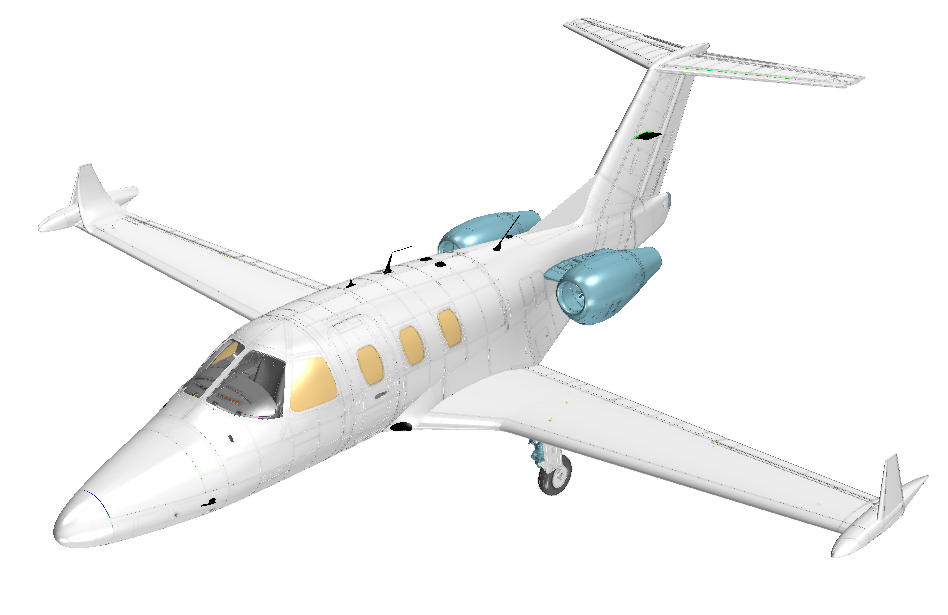
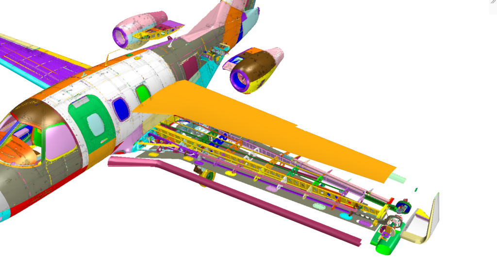
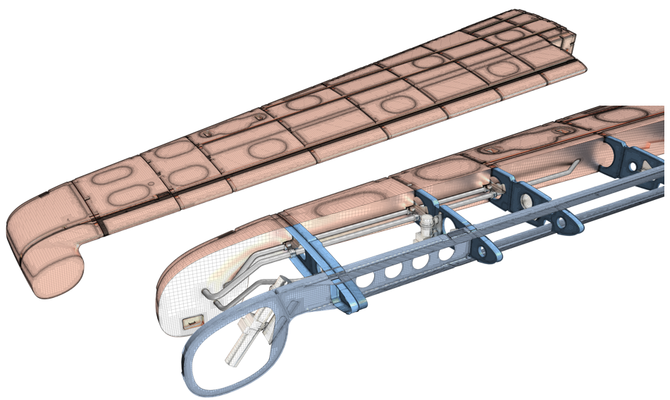
This blog will explore how Simcenter STAR-CCM+ built-in 3D-CAD modeler can bed used as part of the geometry preparation process for a fuel tank slosh simulation of the Bussiness Jet Model, and optimize the pump’s blade design for better performance.
1. Easily Understand and Organize CAD for Simulation
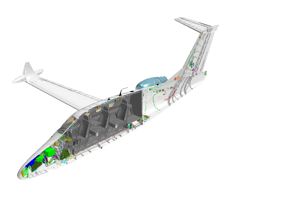
Importing a CAD model and understanding the assembly and design can feel like being dropped into the middle of a corn maze, without any resources to navigate the trails. Luckily, 3D-CAD offers a complete set of tools in the visibility toolbar to quickly understand and organize the geometry.
Let’s start by importing the entire business jet model, which as 16455 bodies, into 3D-CAD. The “section view” and “exploded view” can help you understand, visualize and select the enclosed and challenging parts to view. You can “tag” all fuel system bodies and then use filters to hide them and delete the rest of the model.
2. Repair the Geometry
While importing a native or neutral CAD file from another tool, you may well uncover errors in the geometry, and it can be challenging to identify most of them. This is around the time you may begin wishing for a magic wand to find and fix the issues. Even better than a magic wand is the 3D-CAD search tool, which allows you to identify the model’s invalid bodies or faces. Refer to my previous blog “Simcenter STAR-CCM+ 2019.3: Hidden in Plain Sight? Not Anymore – 3D-CAD Search Tool” to learn more about the search tool in 3D-CAD.
Out of 222 bodies in the fuel tank model, the search tool can automatically identify 28 invalid bodies. The best practice is to fix these invalid bodies with automatic CAD repair operations like “Repair Body” or “Repair Face”, trying to fix and heal the geometry automatically. If an automatic heal fails, you can use CAD repair tools to fix the invalidities.
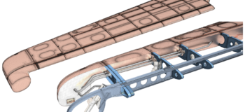
Remove Fillet
3. Prepare the Geometry for Simulation
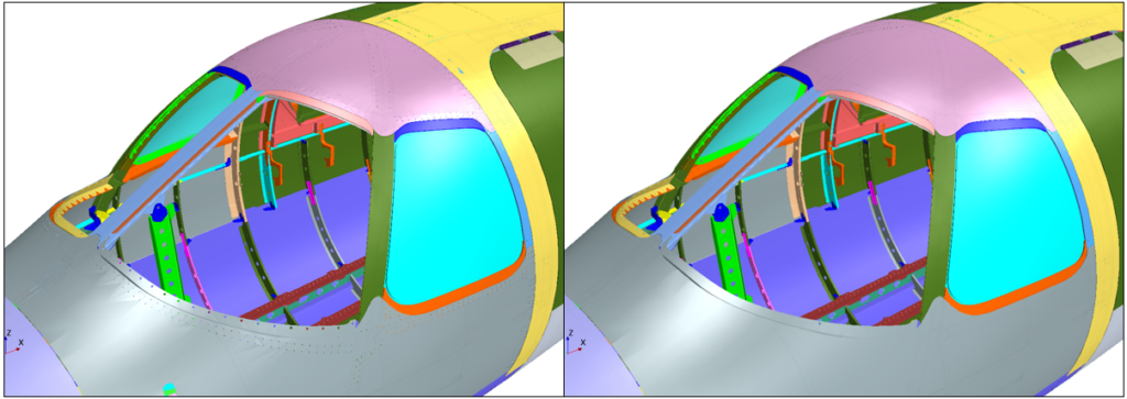
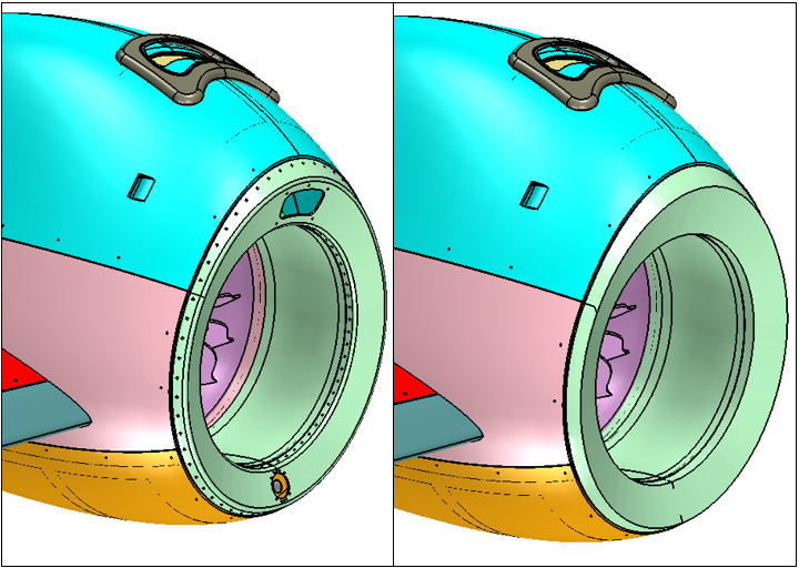
Production-ready geometry typically contains gaps, interferences, fasteners, and tiny features. These features are often necessary for manufacturing but add unnecessary complexity for simulation.
3D-CAD can help here too! The search tool allows you to prepare the geometry by finding similar bodies or topologies like fasteners or unwanted pockets for easy removal, as well as detecting and visualizing clashes or gaps – easily fixed using the extend solid operation. The advanced defeature options allow removing unwanted components with just a few clicks.
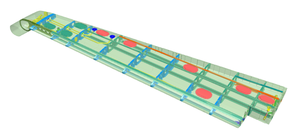
For flow simulation, the ‘wetted surface’ needed is usually either the external volume surrounding the geometry or an internal fluid volume. In the case of the fuel tank model, unite all the internals bodies and subtracted them from the tank volume.
4. Generate Mesh and Simulation
Once the flow domain is created, the (historically) the hard part is done. All that remains is to add a single automated mesh operation in the mesh pipeline to generate the surface and volume mesh.
That was quick – but the acceleration is noticeable when a revised design arrives for analysis. Because the whole process, from geometry import to fluid volume extraction, was done in the 3D-CAD modeler, the sequence of operations was stored and is easily re-executed on the new CAD files in just a few clicks. Now you are ready to go far as well as fast!
5. Design Exploration with 3D-CAD Parameterization
With the 3D-CAD modeler, the entire geometry preparation and parameterization process is capture as an operation pipeline. Any update or design change can be accommodated with minimum manual effort. users can quickly set up and evaluate many operating conditions and designs with just a few clicks using a built-in design exploration feature called Design Manager. To design better-performing products and beat your competitors to market at the same, you need to be able to move from running 1 to 100s of simulations at a time. Refer to my colleague Bahaa Haddoukessouni’s blog “From design exploration to design thinking in 100s of simulations” to learn more about the Design Manager.
In the case of a better design of the pump, the biggest challenge is to get a realistic, yet robust, parametric definition of the impeller blades. Again 3D-CAD features like 3D-Sketch, loft, and extend solid allow to create the parameterized blade. Adding Design Manager allows running multi-objective optimization with parametric impeller for better performance gains. The design Manager was able to find a number of designs that performed better than the original design in one or both of the output objectives of Head and Efficiency.
Going far and fast, together
It turns out that this is about much more than overcoming a bottleneck in the simulation process. It is about unlocking the power of simulation. Using a fast, robust, and repeatable geometry preparation process in 3D-CAD, you can now spend more of that valuable engineering time on just that – finding better designs and delivering value for your business.
So, if you’re not already using 3D-CAD in your workflow, don’t be shy to give it a try!