Measure the unmeasurable using Simcenter Testlab Virtual Point Transformation

Introduction
As test engineers we often find ourselves facing challenges that seem unavoidable when it comes to capturing accurate data. Who has not been frustrated by the limitations of traditional measurement techniques? Whether it’s the lack of physical space to complete the necessary instrumentation or the inability to directly measure certain quantities like rotational Degrees Of Freedom (DOFs), these limitations can significantly hinder our ability to fully understand and analyze complex systems. What if we could measure something that’s unmeasurable?
Dealing with the practical limitations of testing
As the automotive industry continues to evolve and adapt to new technologies, two prominent trends are forcing us to confront these limitations with increasing frequency:
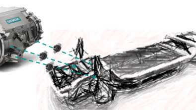
- Digitalization is requiring test and CAE engineers to collaborate more closely than ever before. CAE models driven by real-world test data ensure accurate and reliable performance evaluations which can be quickly iterated upon. However, due to space restrictions, test engineers often struggle to acquire data at the connection interfaces used in CAE models. A typical example is the characterization of powertrain loads at the center of the mounts.
- Electrification is increasing the complexity of physical testing. The compact nature of electric drivetrains and the integration of various components create challenges for accessing and instrumenting certain areas during testing. Additionally, electric drivetrains operate at higher frequencies, where both translational and rotational coupling DOFs may be needed to accurately model the full system behavior.
As digitalization and electrification continue to shape the automotive industry, the need to overcome their associated challenges is becoming increasingly clear. Having unmeasurable locations for sensors is not a valid excuse anymore, so how can we measure the right data?
Time to innovate with virtual points
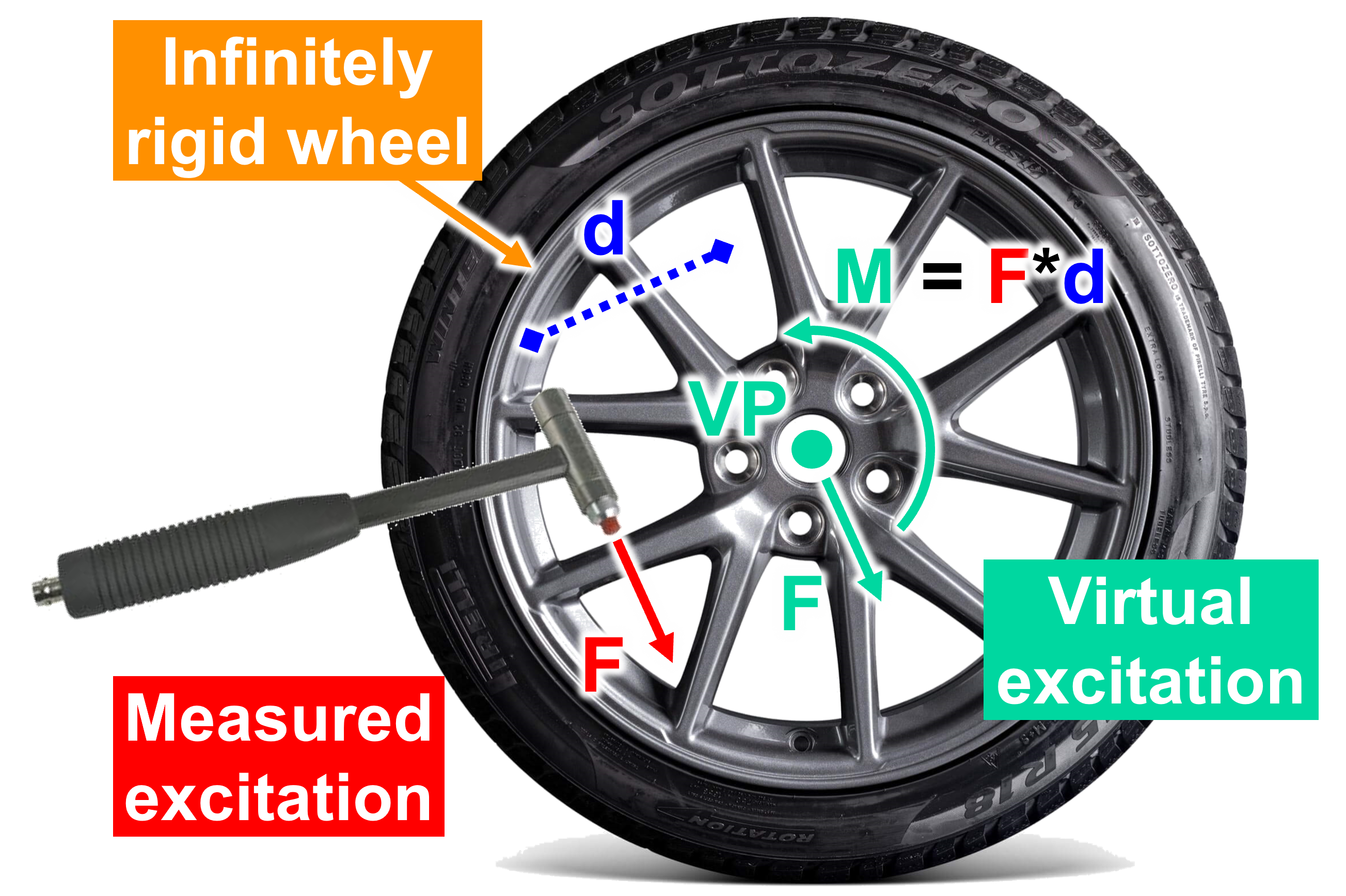
This is where Virtual Point Transformation (VPT) comes in. VPT is a technique for transforming measured data from any (accessible) measurement point to any unmeasurable (arbitrary) ‘virtual’ point. The basis for this transformation is that we can assume that any measured structure will behave rigid locally up to a certain frequency. In that case, measured quantities at the measurement points are linked to the unmeasurable virtual point based on purely geometric relationships.
With VPT we can create a massive impact on the measurement process by simultaneously addressing two key challenges:
- Any arbitrary location can be used to define the virtual point, including inaccessible and unmeasurable locations like the center of a powertrain mount.
- Rotational DOFs are automatically obtained as part of the transformation, due to the geometric offset between the measurement point and virtual point.
A real-life example
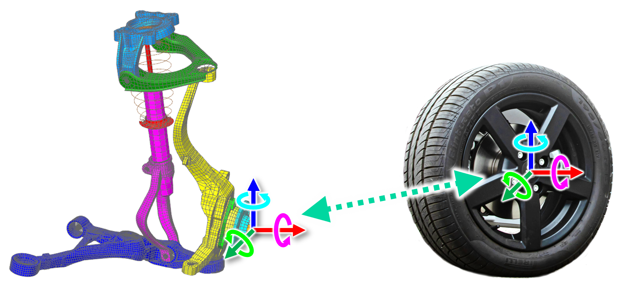
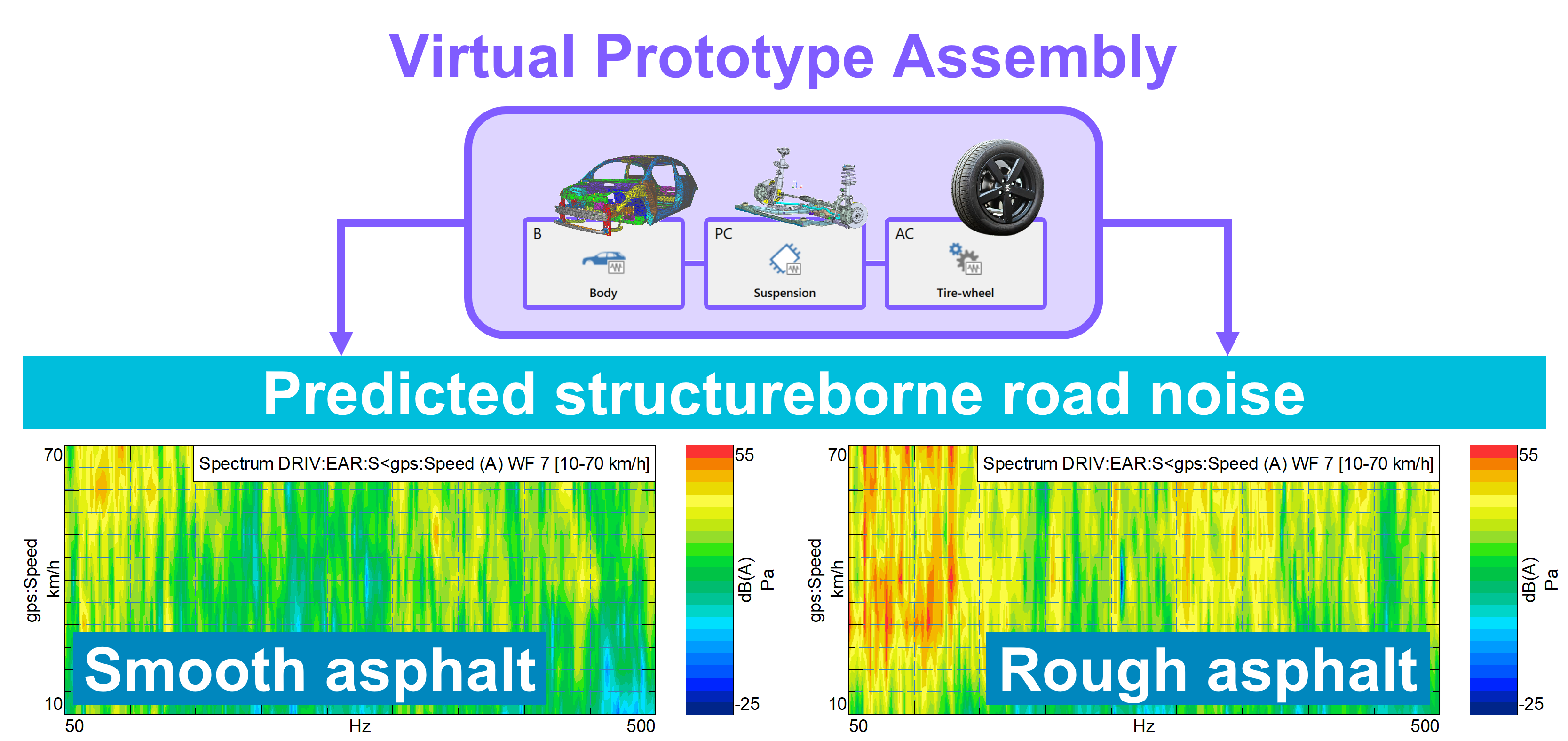
Imagine you want to predict the structure-borne road noise performance of a new vehicle in an early design stage. Using Component-based Transfer Path Analysis we can perform a test-based characterization of an existing tire-wheel set and virtually couple it to a CAE-based suspension model at the center of the wheel hub to predict the NVH performance of the virtual assembly. The tire-wheel is detached from the vehicle and placed in a fixed-free test bench where the correct boundary conditions can be applied. Notice how the connection interface is unmeasurable?
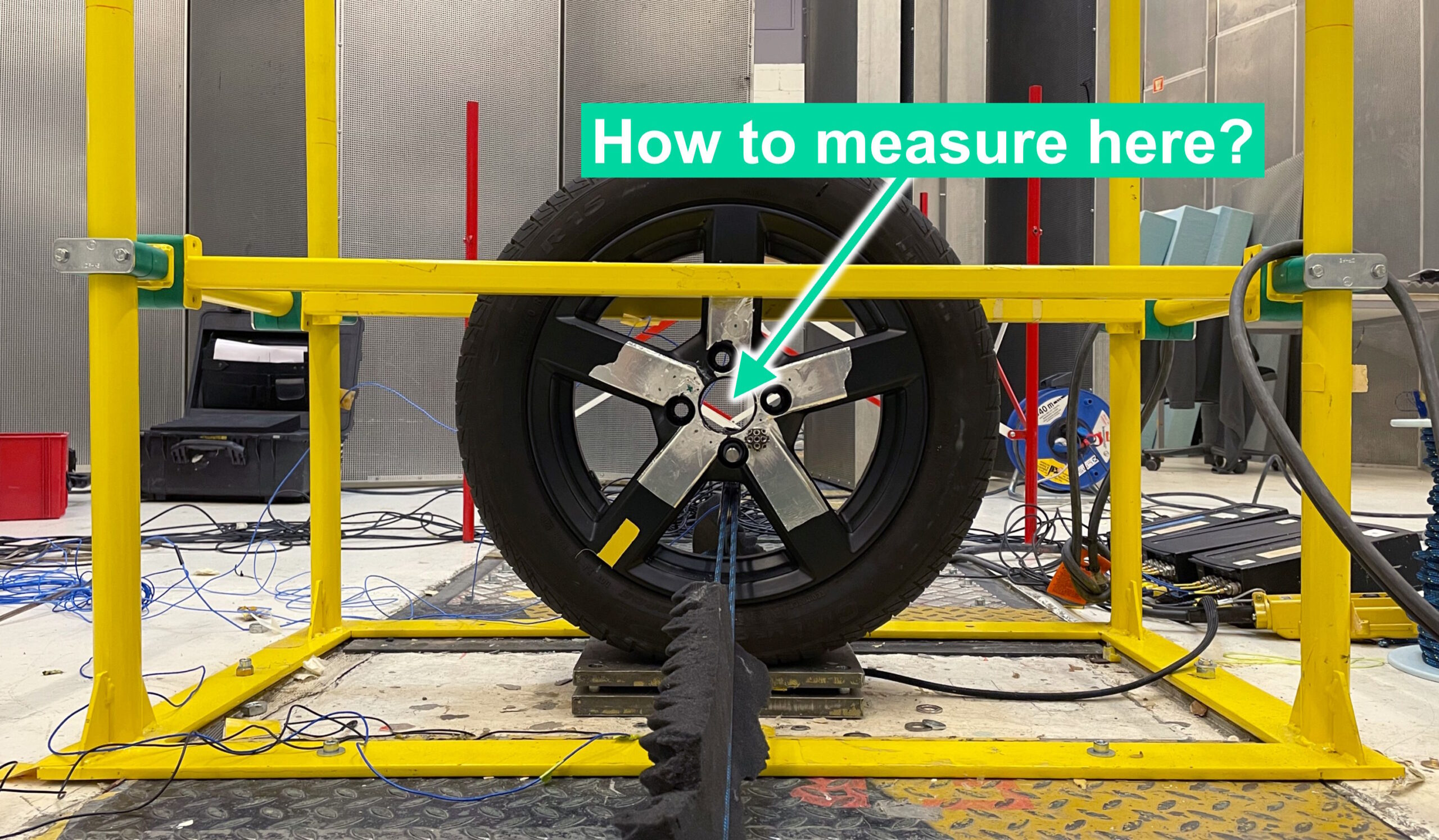
Clearly, we cannot measure anything directly at the wheel center because there is nothing to attach sensors to. Even if it were possible, we would be limited to measuring only translational DOFs using traditional sensors (accelerometers, impact hammers, …), while road excitations are known to be significant in both translational and rotational DOFs. The only way forward is to define a virtual point at the wheel center and perform the physical instrumentation on the nearest accessible part: the wheel itself.
In Simcenter Testlab, we can prepare a digital twin of our planned instrumentation on a CAD geometry to validate the expected accuracy of VPT even before gluing a single sensor. Using CAD geometries for this will dramatically improve the quality of the transformation since geometric sensor data can be extracted with much higher accuracy from CAD compared to manually measuring sensor positions and orientations. A second major benefit is that it is just easier: sensor geometric data is extracted instantly and automatically from CAD.
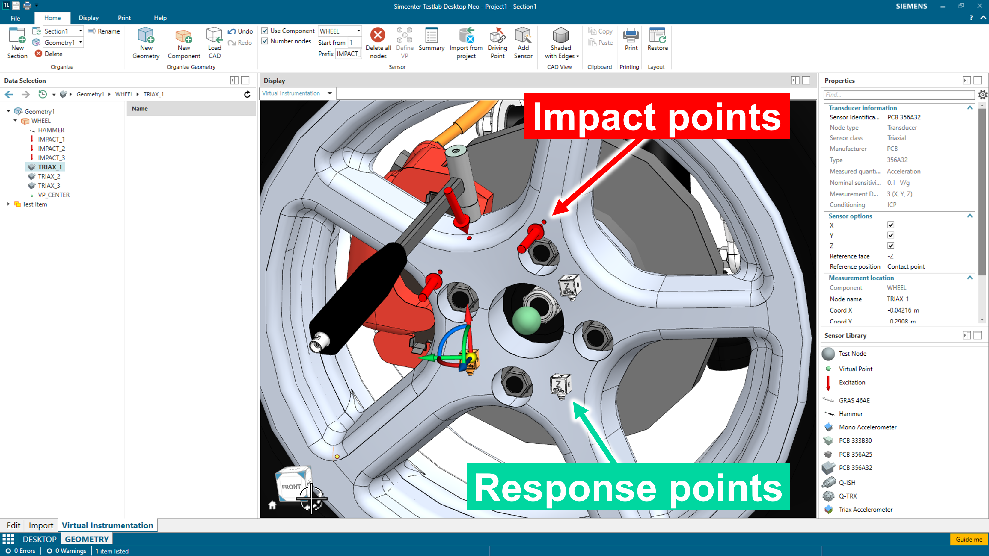
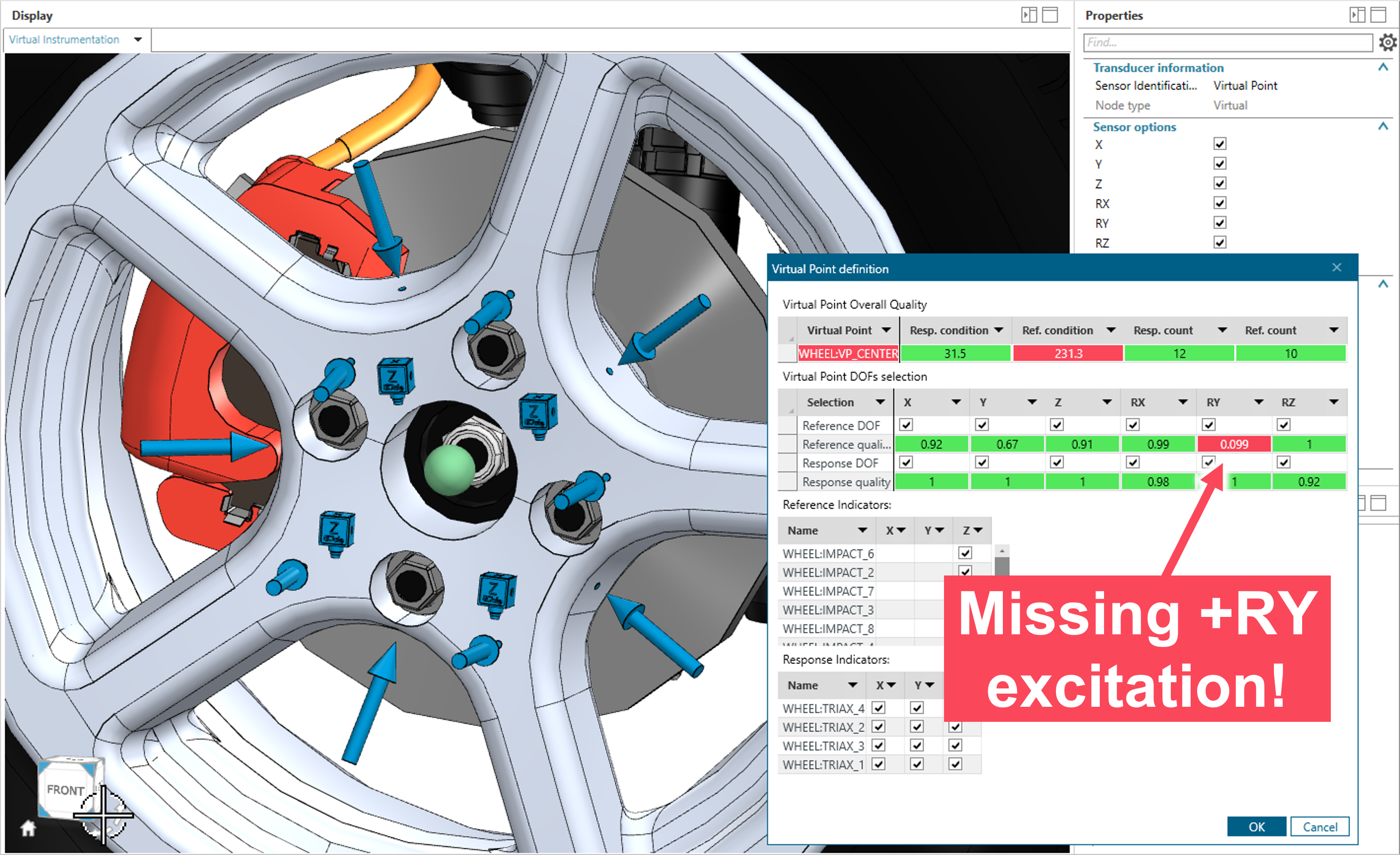
Here we added several virtual accelerometers and impact points to the wheel geometry. Would this be a good setup for VPT? We only want to perform the measurements once, right?!
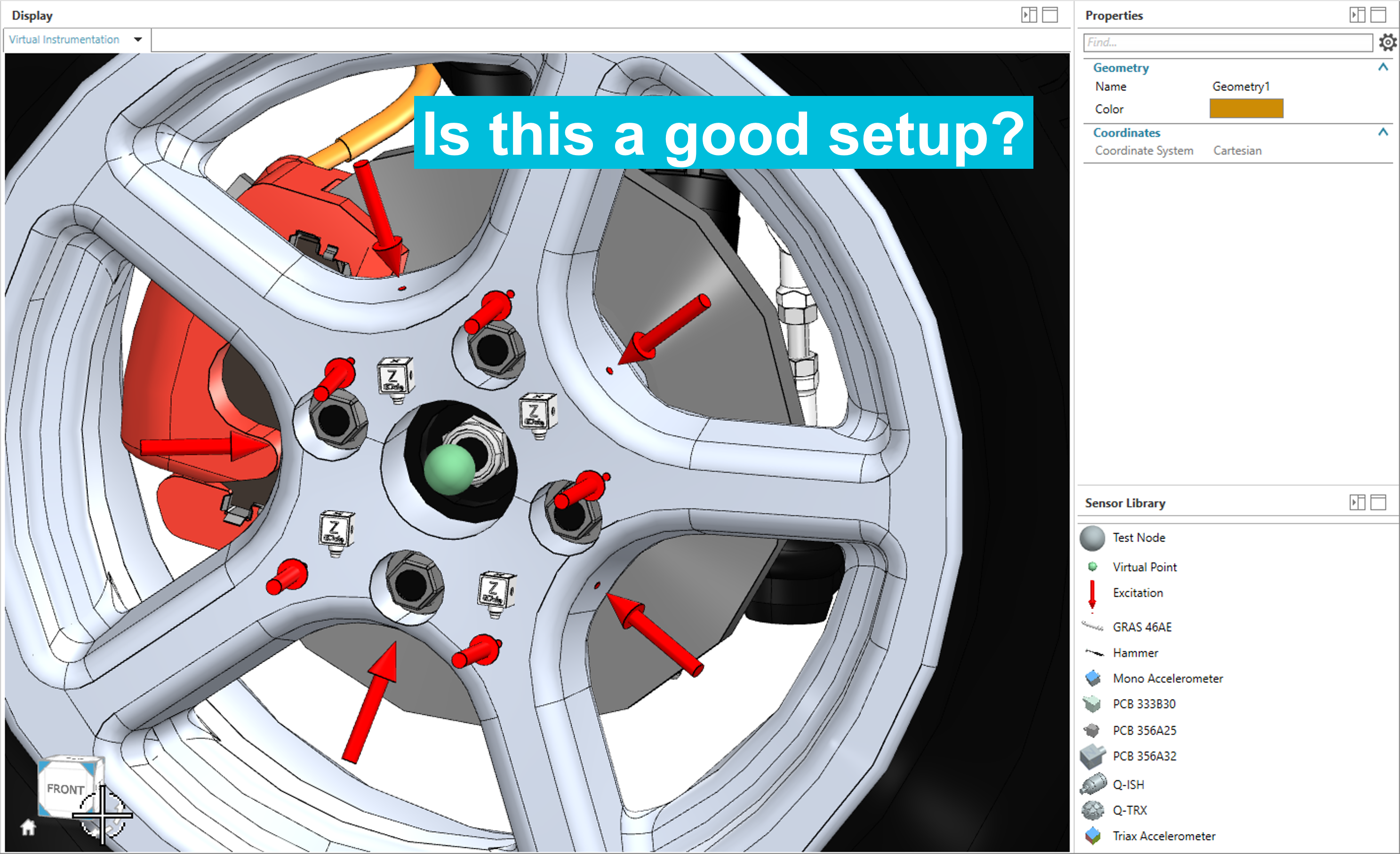
Since VPT depends only on geometric sensor data, we can validate the expected transformation accuracy upfront. Unfortunately, it looks like none of my chosen impact points are exciting the rolling DOF (+RY) of the virtual point.
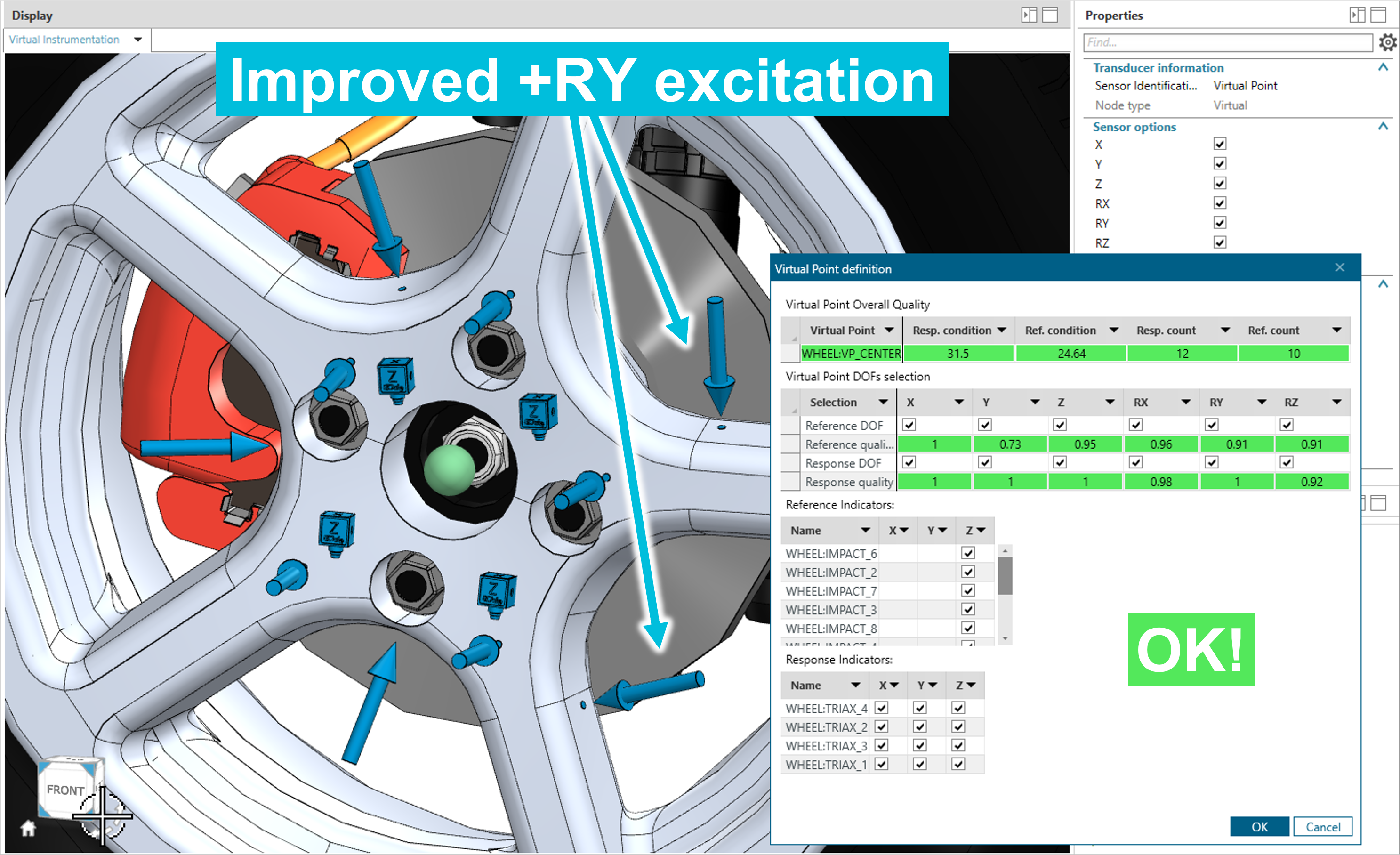
After a quick repositioning of some impact points it looks like this modified setup will work much better. Time to measure!
Trust is good, verifying is better
After gathering all the Frequency Response Functions (FRFs) measured on the wheel in Simcenter Testlab, the FRFs at the wheel center can be calculated using VPT. This calculation happens instantly as the geometric transformations are automatically derived from the virtual instrumentation setup. In this case, the output is an impedance FRF matrix at the wheel center containing all translational and rotational DOFs (6 x 6).
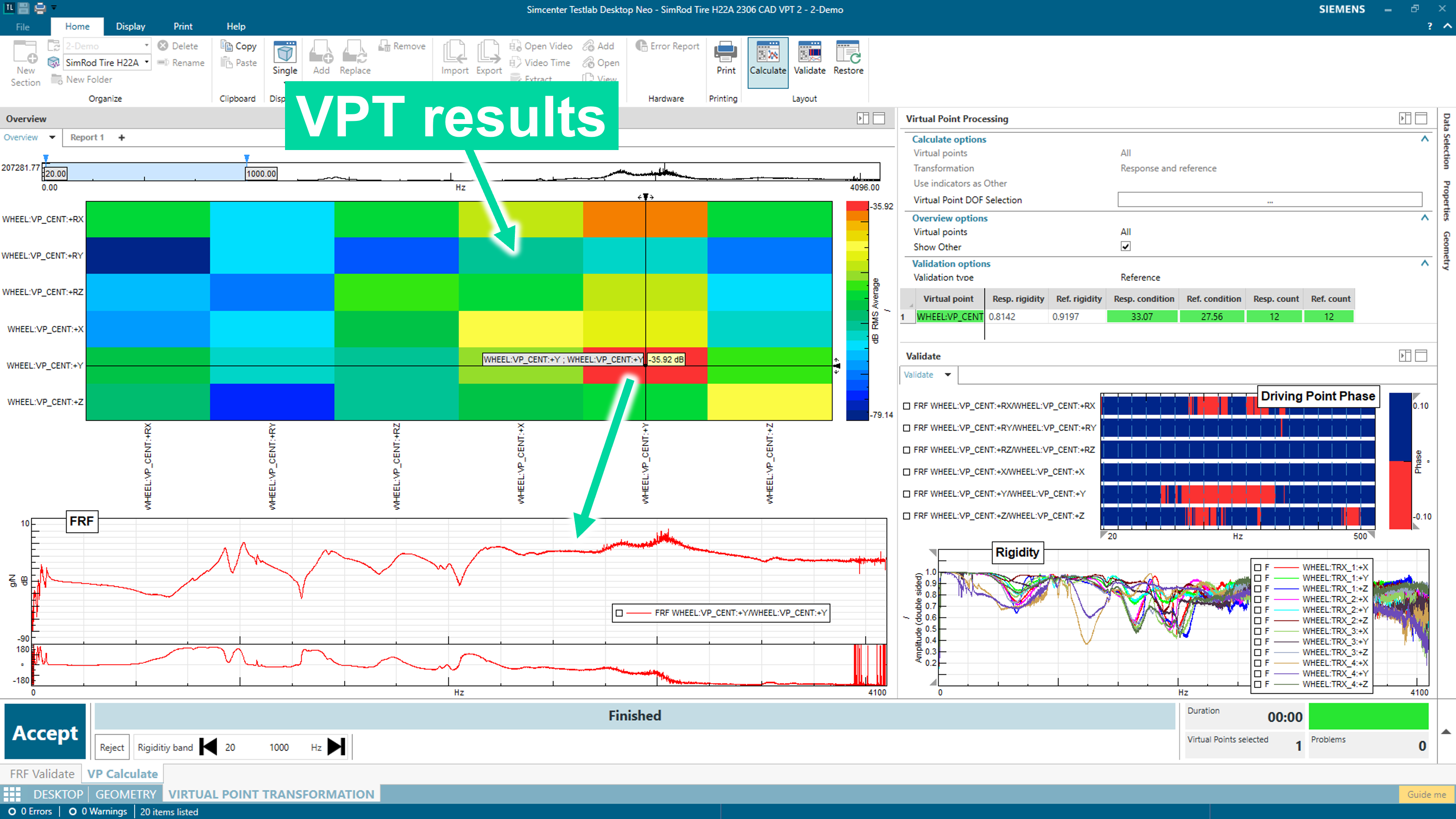
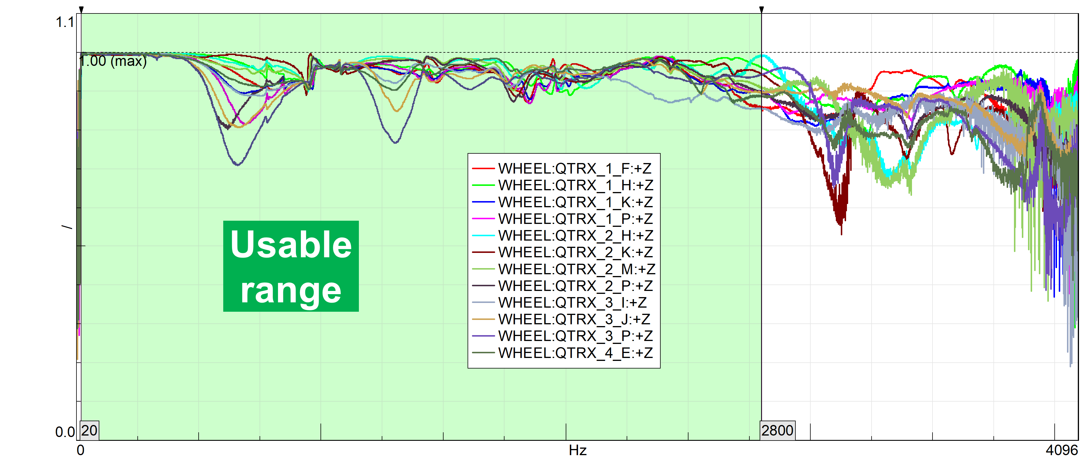
How accurate are these transformation results? To answer that question, we can look at several quality indicator metrics that are automatically calculated during VPT. A fundamental example is the ‘rigidity’ metric which verifies the basic assumption for applying VPT: is the structure locally rigid? This is checked by correlating measured excitation and response data against synthesized data under ideal conditions. In our results it looks like the assumption of local rigidity holds quite well (rigidity close to ‘1’) up to almost 3000 Hz.
In summary, by using VPT we could measure an unmeasurable quantity (translational and rotational impedance FRFs) in an unmeasurable location like the empty wheel center. The accuracy of the transformation and its underlying assumptions could be verified up to several kHz. These results can for example be used to make early NVH performance predictions on hybrid test-CAE virtual prototypes.
What’s next?
Want to start measuring the unmeasurable yourself? Virtual Point Transformation using CAD-based virtual instrumentation is available in Simcenter Testlab 2306.0001.
Are you curious to learn more about NVH performance prediction? Watch our on-demand webinar on how Hyundai Motor Group is virtually assembling vehicle prototypes from test and CAE-based tires, suspensions and vehicle bodies to predict road noise in early development stages.