New dynamic mount stiffness characterization – Why get excited about it?
My colleague’s new toy
Let me tell you why I want to talk today about dynamic mount stiffness characterization. Everything started by discovering my colleague’s new toy in our engineering facility. In fact, I must admit that I was already waiting for it. But in the end, I discovered it on my own, it was standing right there. Working on real objects and being able to bring them physically into the virtual world, are fascinating moments in my work. Let me share one of those with you.

And it starts with my colleague’s new toy. This toy is in fact the new test rig and yes new things are making me curious and excited, especially this one. This is as well a story about small parts being difficult to deal with, and this is the case for engine mounts. But the question is why am I talking about a test rig and engine mounts? Engine mounts have been there for a long time. What can this new test rig more than others?
This is where we start talking about electrification, which has been a hot topic now for a few years in NVH. Even if this topic is already kind of lukewarm. But lukewarm is by the way better to digest. I don’t want to bore you with BEVs anymore. But the new test rig is especially there due to those BEVs and due to an even hotter topic, Component-based Transfer Path Analysis (C-TPA).
A dynamic mount stiffness characterization test rig and what?
Yes, and there it is, still the test rig. And why I am so excited about it, is the fact that it can characterize high-frequency dynamic mount stiffness, and it can use preload. Well yes, those mounts and the rubber materials and nonlinearities are great for decoupling vibrations, but have you ever modeled them? I have, and engine mounts are a challenge for NVH engineers. Because of so many dependencies, like mounts don’t have a linear stress-strain curve, (Young’s modulus will depend on the preload), their dependency on the load-amplitude, temperature, and of course, the frequency.
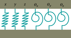
The frequency dependency in particular brings me to another problem, which is the vibration transfer Degrees Of Freedom (DOF). With increasing frequency, we need to consider all DOFs, the translational and rotational DOFs for the mounting. In the end, we have 12×12 stiffness values per frequency to characterize.
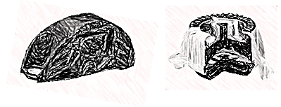
Am I done? No, additionally there are different mount variants, the hydro-mounts, or the elastomer mounts. Now we allow even multi-levels dynamic stiffness models for multi-preloads to cope even better with the nonlinearities and dependencies.
Why a new test rig?
What is the conclusion, can I do my mount characterization with the classical mount characterization rigs? Whether you use the mount stiffness in C-TPA or in CAE models, there are two things that you will need for accuracy. For sure, you need precise high-frequency results for BEVs electric powertrains, and in many cases, you need all 6 DOF (displacement and rotation) characterized. Sadly, most former test rigs cannot do that. They are lacking either frequency range and/or the rotational DOFs. The need for rotating DOFs will depend on the mount stiffness. A very soft mount will not transmit a lot of rotations, though. It will depend on the mount itself, but that is another story. If you can do the above already, that is great. I need to use our new test rigs.
Let’s talk about solutions
Let us say now that we want to characterize the mount stiffness, what do we have to do? We will connect two points by the mount stiffness matrix that has 12×12 entries, linking rotations and displacement DOFs to forces and moments.
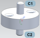
To get the measurement data on precise points, we will use Virtual Point Transformation (VPT). We will do impact testing, measuring accelerations and excite around those virtual points, see below.
How do we fill the dynamic mount stiffness matrix?
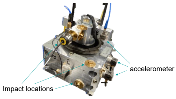
Let me show you how this is done in Simcenter Testlab. Simcenter Testlab allows you to create the dynamic stiffness matrix with impact measurements. It creates the full 12×12 dynamic stiffness matrix and thus eases the task for the engineer.
The impact tests are done on both mount sides. The impact and acceleration locations are transformed into virtual points and the matrix is inverted.
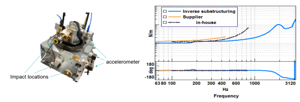
Finally, we get the quality criteria for stiffness and driving point phase and the results of the dynamic mount stiffness, the ones we wanted from the beginning.
By the way, the utilized method uses inverse substructuring and comes up with a few assumptions. It assumes no cross-coupling between the linked DOFs, and it assumes a negligible mass of the rubber joint. This makes it easier to extract the dynamic stiffness matrix.
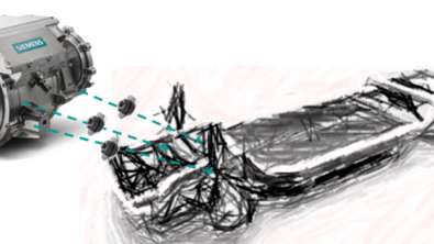
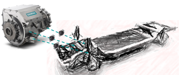
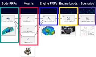
One example is shown in the below project in [1], where we used the engine mounts for a C-TPA analysis.
But now back to my colleague’s new test rig. Because, until now, we might not understand why it is so important to me. But here is the missing puzzle piece.
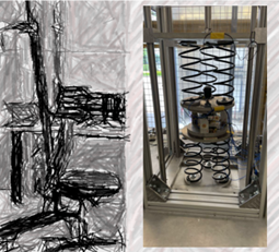
The new test rig
Finally, I am where I started. I have shown you, how you can get the dynamic stiffness matrix, quite easily with impact testing. But the measurement set-up hangs loose and, as we know, the mount stiffness is changing with the loading condition. And now you know why this new test rig is so interesting to me. The preload adds accuracy. One could even use different preload measurements to account for different preload states, improving even more the model accuracy. So now you know, the new test rig allows me to model my mounts closer to reality…
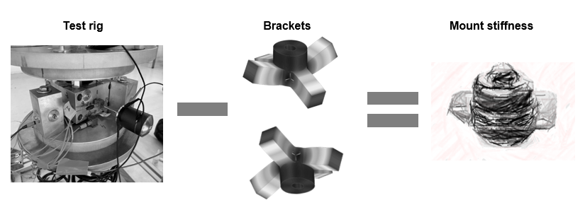
A good thing to know is that besides inverse substructuring, I can use FBS decoupling as well to get the mount stiffness matrix. FBS decoupling requires a model of the brackets, measured, analytical, or simulated, so more engineering work. Results will depend on the brackets model accuracy and might be equal or more precise than with inverse substructuring, see in the image below how it works.
Now you know why I am that excited? All that I can get from the new test rig and with the above dynamic stiffness matrix characterization.
In the end, what do I want to do with it?
I want to reassemble component-wise a vehicle with different powertrains, different bodies, and different passive components. With that I can play around with the vehicle variants, listen to them, and compare them as if I were measuring a prototype. All this with C-TPA and Virtual Prototype Assembly (VPA) and the new test rig for mount stiffness characterization.
Let us work together…
Are you using C-TPA or VPA or are you wondering if your CAE models would be more precise with a high-precision mount characterization and have all 6 DOF connections for your mounts? Then please don’t hesitate to use this link to learn more about our software solutions.
Or contact our engineering service team for help, on how to use those new technologies for your specific application!
Do you need advice for your measurement set-up, or would like to see if with Simcenter Q-sources you can improve your measurement accuracy?
I think it is time to contact us!
markus.brandstetter@siemens.com
[1] Wagner P, Bianciardi F, Corbeels P, Hülsmann A. High Frequency Source Characterization of an E-Motor using Component-Based TPA. InProceedings of the SIA Automotive NVH Comfort Conference 2021.


