Simcenter 3D 2512: Active magnetic bearings in turbomachines
Introduction
Using Active Magnetic bearings in turbomachines has many benefits. High-speed turbocompressors, pumps, and turbines utilise them to reduce friction in the system, thereby boosting efficiency and increasing the machine’s lifetime. In such turbomachines, the shaft is maintained in levitation in the electromagnetic field inside the bearing housing. This is possible thanks to digital controllers that control the applied electromagnetic force on the shaft, from the vibrations measured at a sensor location, and a transfer function.
Simcenter 3D advanced capabilities for active magnetic bearings
In Simcenter 3D 2512, you can now define active magnetic bearings in your rotor dynamics simulation. The active magnetic bearing uses a magnetic pull and a digital controller that monitors a sensor node for rotor displacement. The digital controller sends the displacement through a series of analytical functions and then sends the result of these functions to an actuator node, which uses a force load to adjust the position of the rotor. The effects of the magnetic bearings can be observed on the Campbell diagram, in the complex modes, and in the system’s response in the frequency domain.
Active Magnetic Bearings Workflow
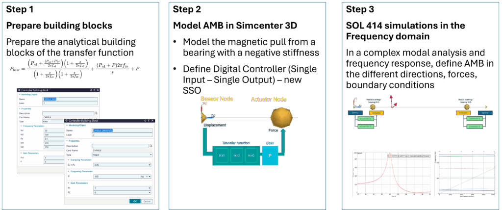
Step 1: Prepare the transfer function of the controller
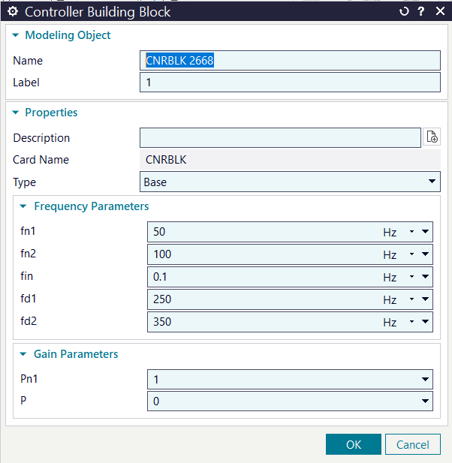
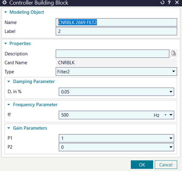
The transfer function of the controller, F(s), can be composed of one or several analytical functions, encapsulated in controller building blocks. Prepare the controller building blocks by choosing your desired types of analytical functions and set their parameters. Optionally, building blocks can also be imported from an existing simulation.
qout = F(s)qin
Where:
qout is the actuator output (force) in the laplace domain
qin is the sensor input (displacement) in the laplace domain
F(s) is the laplace transform of the transform function, with all initial conditions assumed to be zero
s is the laplace variable
Step 2: Prepare the model and the digital controllers
Model the magnetic pull from a radial bearing or bushing with a negative stiffness
Prepare the Digital Controller (Single Input – Single Output) by selecting the sensor node, the actuator node, their components, a value for the gain, and the selection of one or multiple building blocks. If multiple building blocks are selected, the corresponding transfer functions are multiplied.
Simcenter 3D modeling capabilities for rotors, such as 2D Fourier model or super-elements, can be used with the new digital controllers.
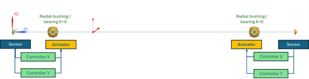
Step 3: Simulation with a SOL 414 analysis
Active Magnetic bearings are enabled for complex modal analysis or for forced response in the frequency domain. Their effects can then be seen on a Campbell diagram or response functions of the system under synchronous or asynchronous loads.
Related blogs on rotor dynamics
Did you enjoy reading this blog and want to know more? You may also like the following blog posts:
Rotating systems – tune your intuition
Efficient rotor dynamics for multi-stage turbo machinery
Containing aircraft engine failure
Combine solution speed and accuracy for axisymmetric rotor dynamics
Bearing modeling makes or breaks rotor dynamics simulation
Multi stage cyclic symmetry in rotor dynamics
Advances in resonance and cyclic symmetry of bladed rotor assemblies
Identify the peaks of harmonic response during operation of nonlinear rotor dynamics
Smooth vibrations in rotating systems – How to monitor clearance consumption
Turbomachine assemblies and the challenges of designing them


