Powder Bed fusion: Simulation with an iterative approach to improve compensation.
Powder Bed Fusion is a layer-by-layer and line-by-line welding process. Like any other welding process, it will create large amounts of thermo-mechanical stresses between the single layers. These stresses will, in most cases, lead to distortions in the printed part.
Even if these stresses don’t cause your part to crack or the support structures to fail, a deformed part still might be unfit for purpose because it will not fit the assembly or function as planned.
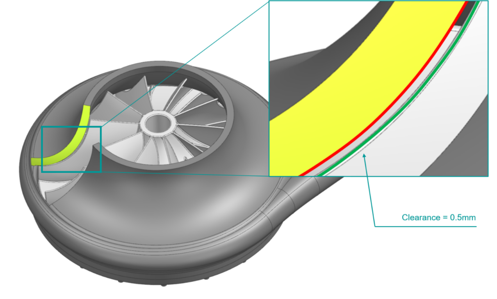
As-printed distortions vs. assembly clearance
For instance, when printing impellers via powder bed fusion, the thermo-mechanical stress may lead to large distortions of thin blades. Distortions can vary over the length of the blades due to the varying stiffness and angle towards the build plate. Powder Bed Fusion simulation with Simcenter 3D allows an engineer to simulate and visualize these distortions.
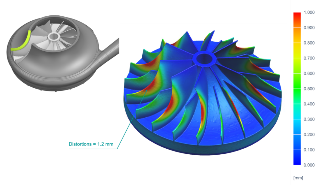
The clearance and the angle of incidence between the impeller blade tips and the casing substantially influence a machine’s efficiency and power. The smaller the gap between the casing and blade tips, the higher the pump’s or turbocharger’s efficiency. The desired clearance between blade tips and casing will often be 0.5mm or less. However, during the printing process, the blade tips will deform, up to 1.2 mm in our case. A possible solution would be to add extra material on top of the blades and have them machined to size. With Simcenter 3D for Additive Manufacturing, the user can simulate the printing process and calculate these distortions before printing.
We can use the calculated distortions to pre-deform the geometry so that the printed part will eventually have the net-shape of the original geometry. We call this process compensation. To complete the Compensation process, engineers often use a static factor (e.g., -1). They simulate displacements and subtract them, using the static factor, from the CAD model to get the compensated model.
Iterating towards the best Powder Bed Fusion compensation
However, compensation with a single factor may not always yield accurate results for parts with large deformations and multiple deformation modes because a compensated geometry might distort slightly differently from the original one. For this reason, Powder Bed Fusion simulation in Simcenter 3D offers the possibility to use an iterative compensation solution. The iterative compensation solution allows engineers to simulate the part, compensate, and then simulate again. The resulting deviation between the printed part and the original CAD geometry is analyzed and compensation is repeated until the desired accuracy is achieved.
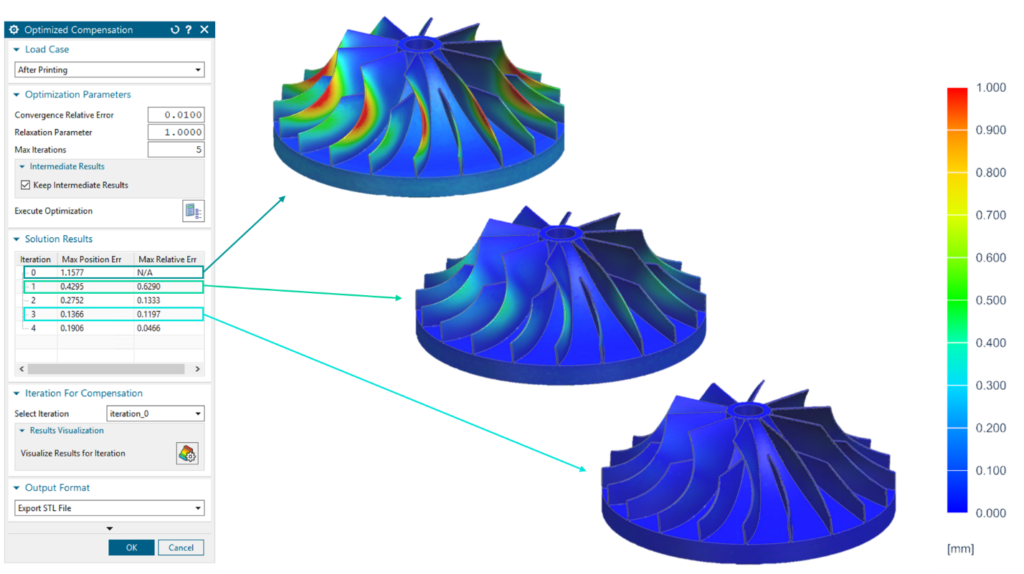
We call this solution the Optimized Compensation, which allows the iterative compensation of a part and the user to track, analyze and visualize all intermediate iteration steps.
The user can then choose whether they are satisfied with the resulting compensation and the simulated deviation from the original CAD geometry or try to re-calculate with a higher number of iterations.
In the case of our printed impeller, the initial compensation decreased the distortions by 60% down to 0.4 mm. With desired clearances of around 0.5 mm, this might not always be sufficient. Only with an iterative approach were we able to decrease the distortions by another 65% down to 0.13 mm.
Sometimes, the iteration results may also oscillate around a good solution, so the last iteration does not always yield the best result. Optimized compensation allows the user to select any of the iteration steps to generate a compensated model of the part.
Finally, the compensated model can either be exported as a faceted STL, based on the finite element mesh, or as a surface-morphed solid NX part, via the optional OmniMesh transformer add-on.
Blogs Related to Powder Bed Fusion
Prevent excessive build plate distortion in additive manufacturing