How to Design a Heat Sink for Additive Manufacturing
Over the last decade, additive manufacturing has become increasingly popular in the world of engineering. Especially in the world of electronic design and cooling where we are no longer limited to the conventional plane and pin fin heat sinks of old. With the advancements in 3D printing, we are now liberated to be more creative and progressive with our designs.
In this blog, we, the current 2021 Siemens DISW interns, will discuss our entry into the 2021 ASME/IEEE heat sink design competition. We will also showcase some unique designs which are only achievable with additive manufacturing and compare their performance based on thermal CFD simulations carried out in Siemens Simcenter Flotherm XT software.
The heat sink design competition
Each year, university students across the world compete in the Heat Sink Design Competition organised by the ASME K-16 and IEEE EPS organisations. The 2021 competition tasked students to get creative and design a heat sink subjected to natural convection, whilst leveraging the power of additive manufacturing. The successful finalists had the opportunity to get their aluminium heat sinks 3D printed in collaboration with General Electric Additive and had the chance to present their designs virtually at the iTherm 2021 conference in the USA. This was an exciting challenge for us student interns, which could not be missed, so we quickly got to work on creating our own innovative designs!
Concept designs to leverage additive manufacturing possibilities
The initial design cycle began with each of us interns coming up with our own design concept for a heat sink. This meant brainstorming our ideas with good old-fashioned pen and paper, long before starting any CFD analysis! This resulted in some hand-drawn sketches which we collectively shortlisted down to just 6 designs that were chosen for CFD modelling.
Each of the 6 shortlisted designs were modelled in CAD and simulated using Simcenter Flotherm XT as a natural convection scenario. The model setup and boundary conditions for all the designs were identical, i.e. the same benchmark heating applied at the base of the heat sink and the same ambient conditions. This enabled us to compare the designs quantitatively using a relative performance parameter based on our Simcenter Flotherm XT results. The performance parameter accounted for both the heat transfer efficiency and the mass of the heat sink.
So, without further ado, here are the 6 shortlisted designs:
Design 1
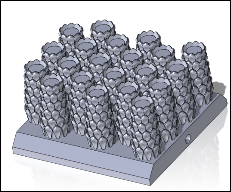
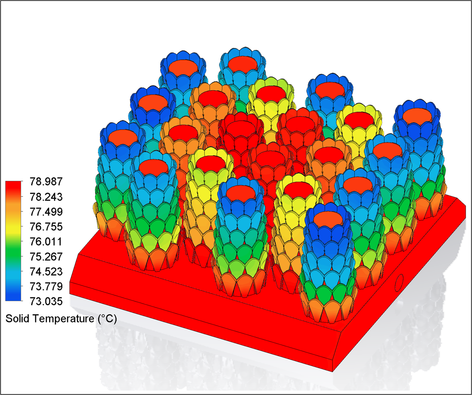
The first design was inspired by a pine cone structure which enables a large surface area in a confined space. The primary modes of heat transfer for heat sinks are conduction and convection, which are heavily influenced by surface area, and so what’s not to like about this geometry? Through the CFD analysis, we realised that due to the dense packing of pine cones, there was heat accumulation in the centre of the heat sink, a sign of not enough air movement. In addition, due to the high mass and thus higher material costs, this particular design had the lowest performance parameter.
Design 2
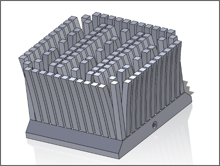
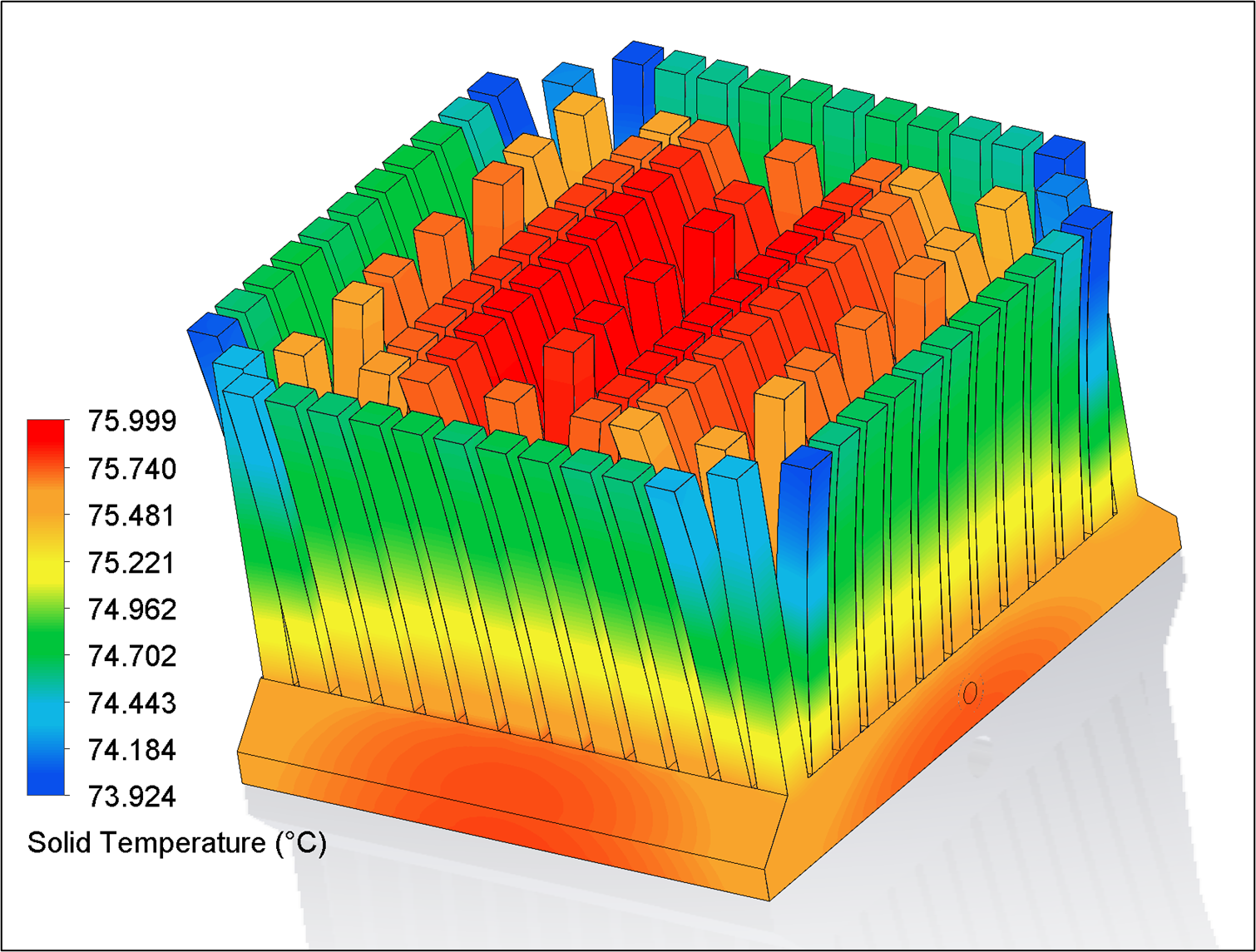
Generally, there is always room for improvement in existing technologies to have greater efficiencies. With that in mind, our second design was motivated by the existing, most common, pin-finned heat sink. In this case, the intention was to arrange the pins in a unique fashion which can allow more surface area and therefore, better heat transfer efficiency. The performance of this design was better than the first, however, due to its high mass, it still did not have the best performance parameter of all the designs.
Designs 3 & 4
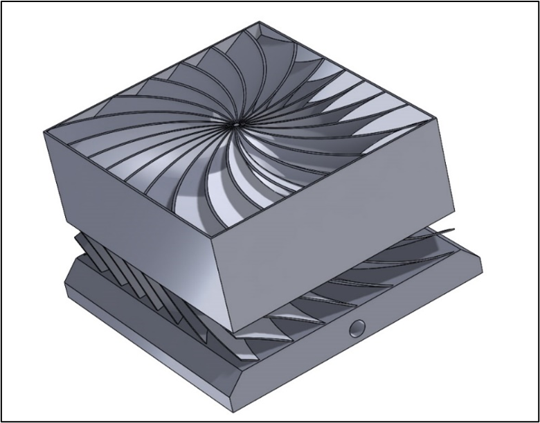

Whilst leveraging the power of 3D printing, which has the ability to capture intricate details and create thin smooth curved surfaces, two interns came up with Designs 3 & 4 which take inspiration from aircraft fan blades. The basic idea behind these designs was to use the re-circulation and aerodynamic features of fan blades to promote convection. In theory, these designs would work much better in forced convection applications compared to natural convection. Nonetheless, the performance parameter of these designs was similar to Design 2.
Designs 5 & 6
A common reason for the not so spectacular performance parameter of all the previous designs discussed so far, was the relatively high mass of each heat sink. Therefore, Designs 5 & 6 tackled this issue as they were inspired by a lattice-type structure, with lots of empty space!
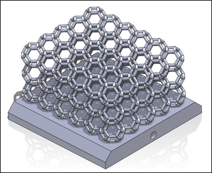
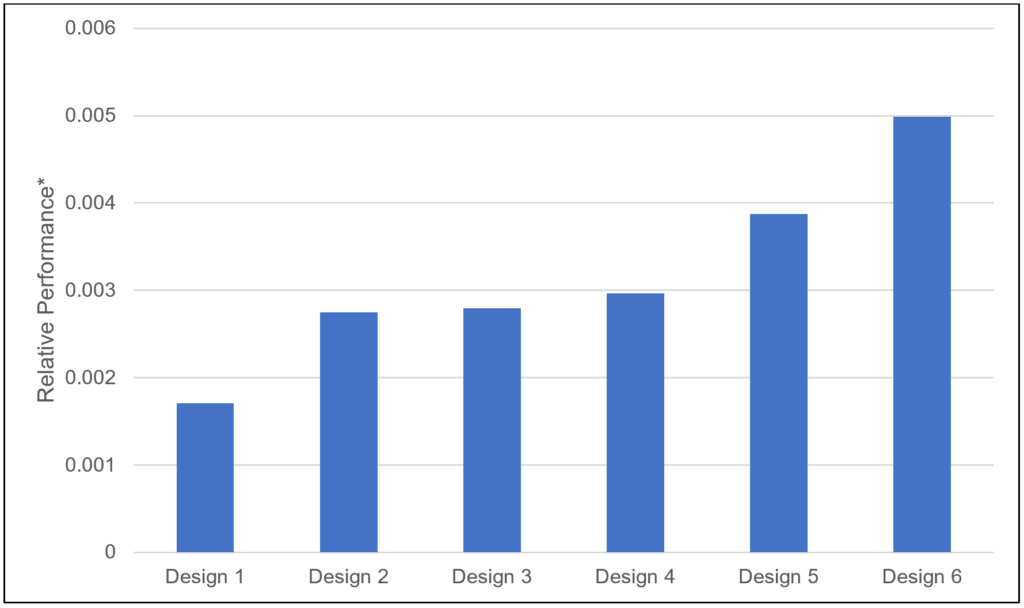
Design 5 was a simple repeating hollow cube structure, allowing enough empty room for air to pass through and also sufficient surface area for heat transfer to the surrounding air. As a result of these two reasons and very little mass, the relative performance parameter was almost 25% better than all our previous concept designs. Design 6 followed in a similar vein, whilst demonstrating more creative use of additive manufacturing with its shape structure, which was inspired by the hexagonal honeycomb found in beehives.
So, with all of our 6 concept designs simulated, the performance for each of the designs is shown below. As you can clearly see, Design 6 was an obvious winner!
Final design
Out of all the creative concepts we came up with for a 3D-printed heat sink, we decided to use Design 6 for our competition entry due to its high-scoring performance results shown earlier.
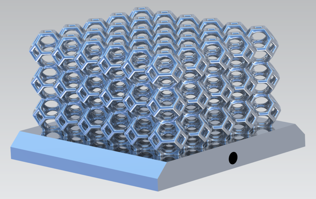
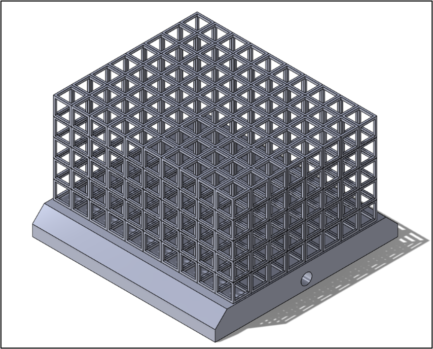
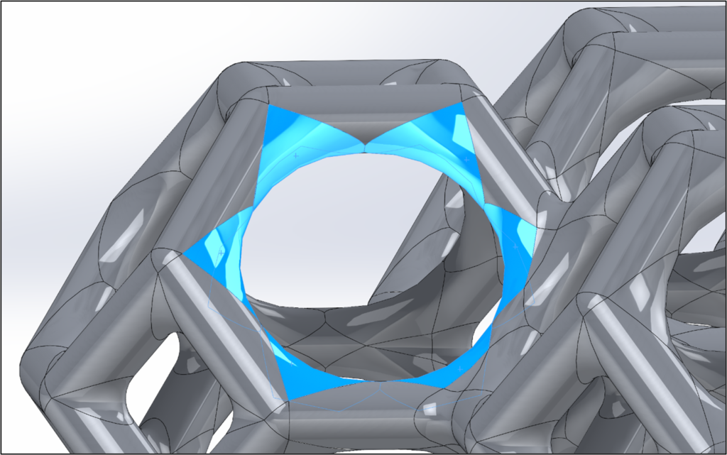
This specific design utilised a truncated octahedron shape in a repeating pattern to form a lattice structure. It gave us a good balance of both solid-conduction material for the heat to flow through the lattice joints, whilst maintaining a significant amount of empty internal space for good airflow and kept the material/mass to a minimum. It also looks extremely cool and would not be easy to manufacture with conventional manufacturing methods!
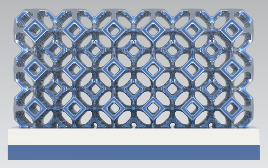
Due to the nature of additive manufacturing where the aluminium layers are built up in a horizontal fashion, it was important to ensure there were no hard edges or unsupported overhanging horizontal ligaments of more than 2mm in the design. This was further supported after discussions with GE Additive, where we were advised about the strengths and weaknesses of Electron Beam Melting. As a result, we added smooth blends to all the edges (and there were a lot of edges!) to help ensure a successful 3D print of our design.
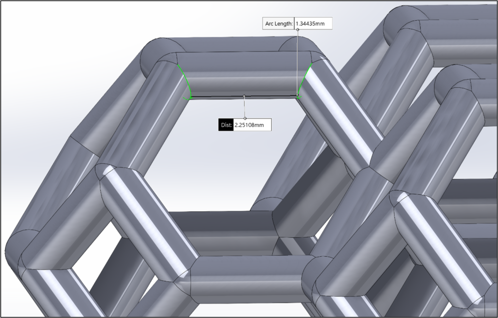
Another trick to avoiding this potential breakage issue is to rotate the whole model at a specific angle during the printing phase. This method is commonly used in additive manufacturing and allows the user to print certain overhanging ligaments at a specific angle whilst not exceeding the 2mm horizontal overhang limit. We decided to take the safest approach and added the blends to our model, as a reliable manufacturing method is always crucial in engineering components, as the saying goes “a design is no good if it can’t be manufactured”.
CFD analysis of the heat sink design
Using the powerful CFD analysis tools available in Simcenter tool portfolio, we were able to see how our final design behaved under the natural convection scenario as required for the competition.
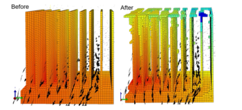
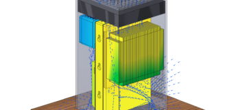
This animation of the airflow vectors demonstrates the lattice’s ability to allow air to flow in and around the internal structure of the heat sink. Also visible from this animation is the “chimney effect” of the hot air rising out the top of the heat sink. This allowed fresh, cooler air to be drawn in at the bottom and side edges of the lattice, providing a steady cycle of fresh airflow for cooling – vital for a natural convection scenario such as this.
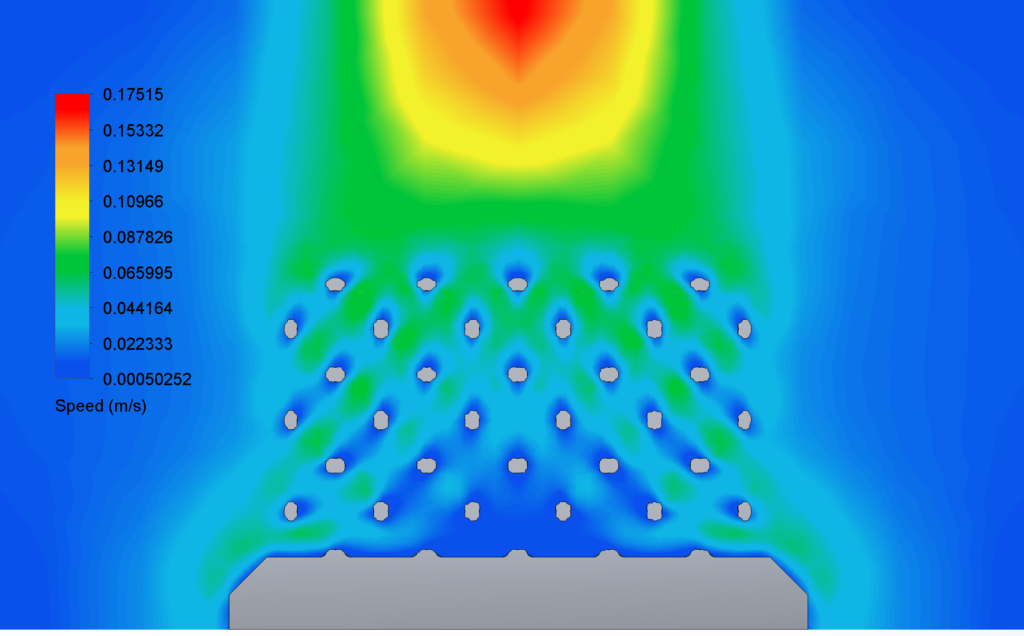
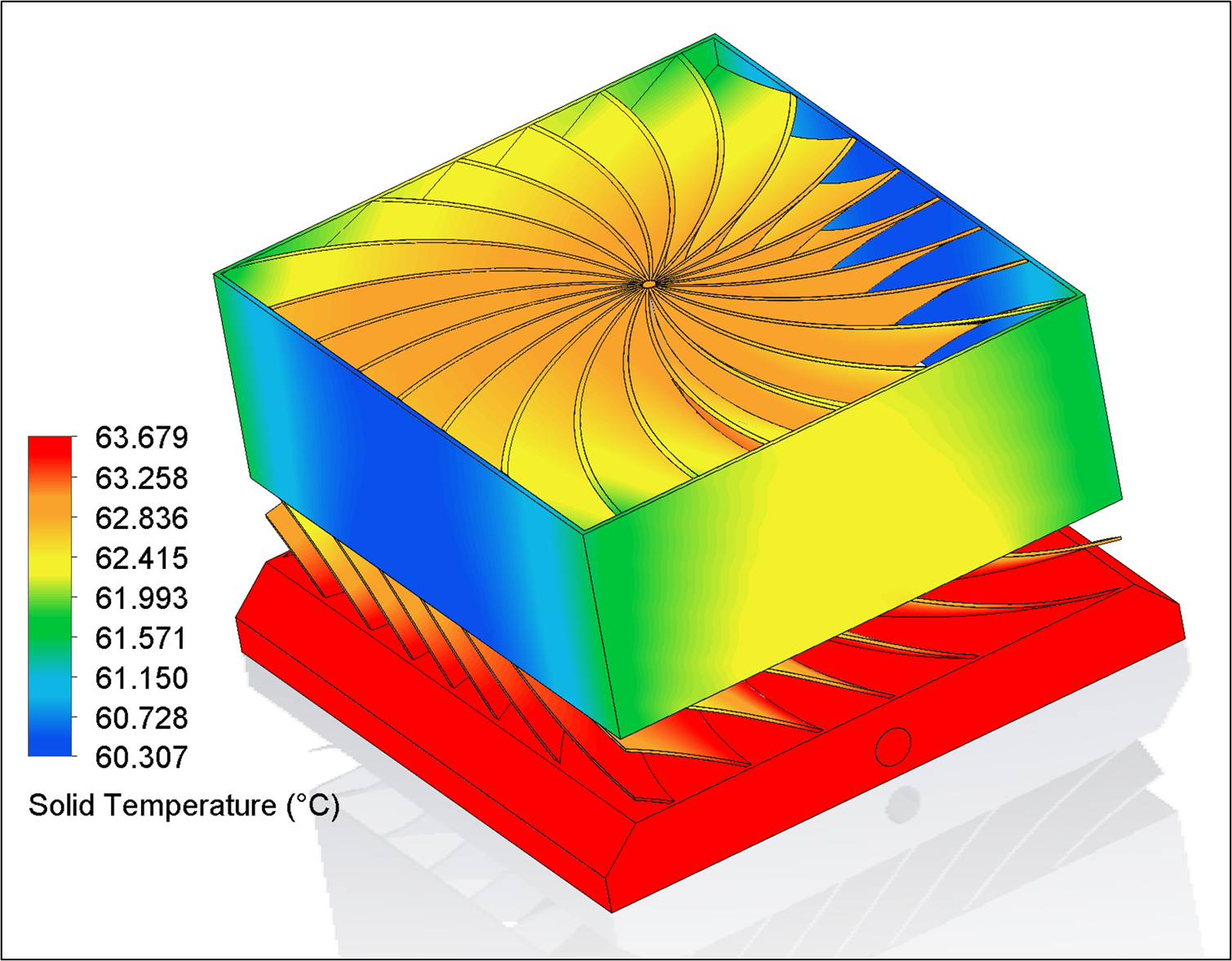
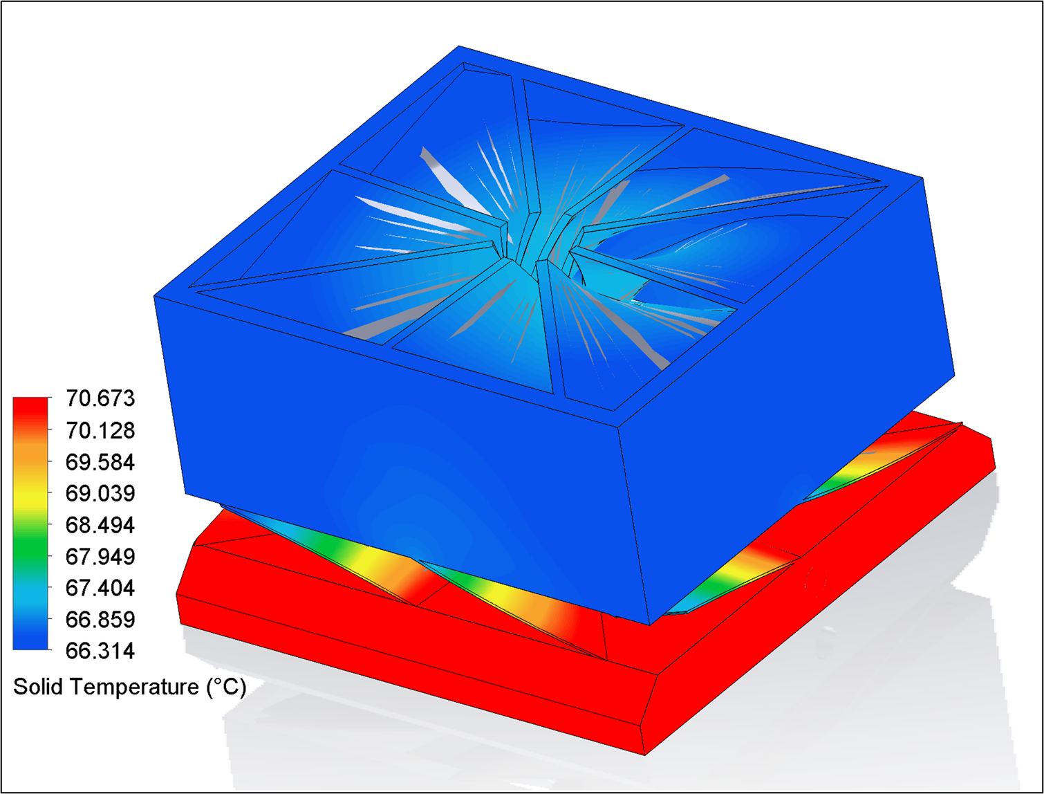
Observing the airflow more closely with a plane plot, we can see that there was a good amount of flow in the upper, middle and side sections of the lattice. However, there was some slow movement of air at the bottom central section of the heat sink, represented in the image above in the dark blue colour. This is a potential area for future improvement, where extra material could be added to improve conduction since not much airflow or convection occurs in this bottom-central section. We chose not to do this as more material = greater cost. So once again, it is a fine balancing act between thermal performance vs cost!
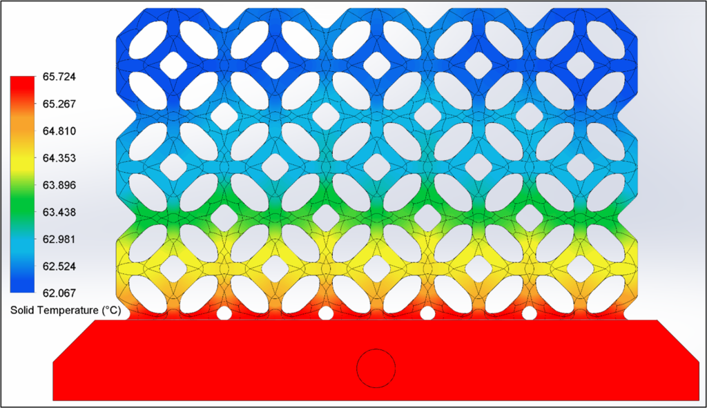
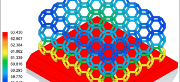
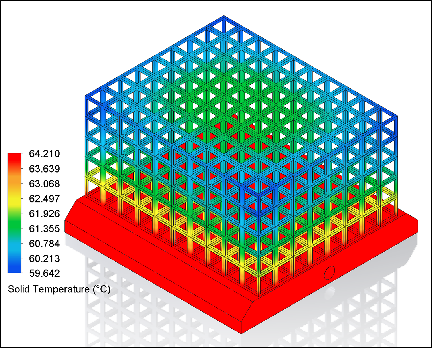
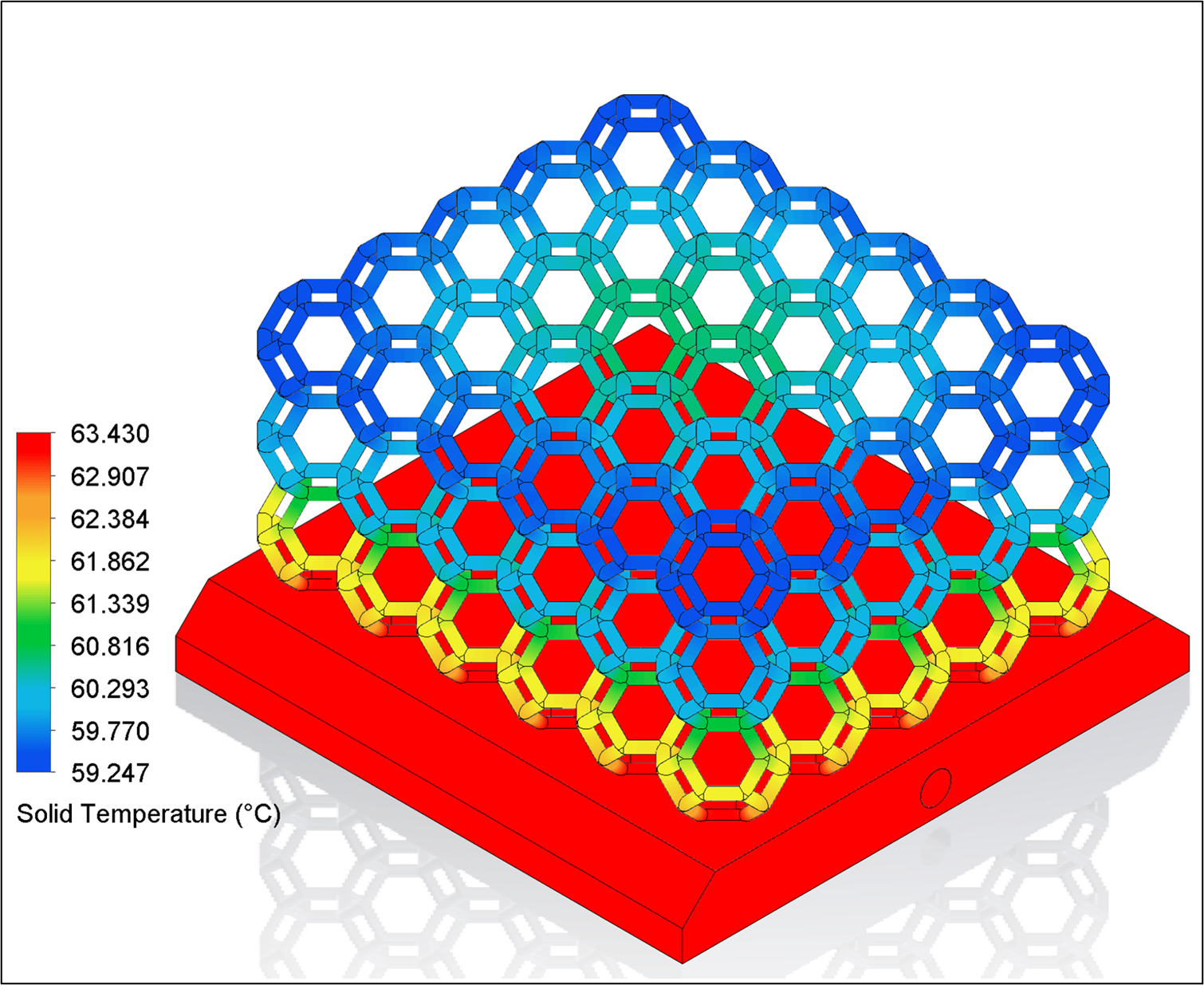
This final and very colourful looking image reveals to us the conduction capability of the solid lattice structure. We can see the hottest base part being 65°C shown in red, with the coolest part of the lattice being 62°C at the very top outer edges shown in dark blue. This reveals a ΔT of 3°C from top to bottom, which means a good amount of heat flux was able to pass from the base all the way through to the top lattice joints without too much thermal resistance caused by the thin joint diameters. This was vital to check on our design, as we were dealing with joint diameters of just 1mm, which was much thinner than conventional heat sinks due to the 3D printing capabilities of additive manufacturing.
The Result
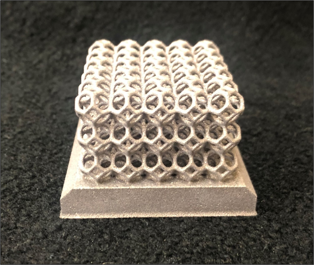
As student interns, we are pleased to say that our final heat sink submission presented here, made it all the way into the top 5 designs of the ASME/IEEE 2021 heat sink design competition. Reaching the finals meant our design was selected for 3D printing in aluminium using state-of-the-art electron beam printing machines at GE Additive:
In addition, being in the top 5 meant that we got to present our heat sink design at the ITherm 2021 conference, held virtually this year over in America. A fantastic result, and a fantastic experience for a bunch of student interns still in training!
Conclusion
The creative possibilities enabled by additive manufacturing are enormous. We have demonstrated 6 unique heat sink designs that would only be possible with 3D printing technology, whilst also explaining the design process behind our final submission that reached the top 5 of the ASME/IEEE 2021 heat sink design competition.
Have you seen any other unique engineering designs which are only made possible through the use of 3D printing? If so, we would love to hear about them. Please share them in the comments section below.
The 2020/2021 Siemens interns (aka Team Turbulence for the design competition) consisted of: Malcolm Johnson, Shivashish Arora, Santhush Thilakaratne, Zakaria Dahir, Remi Khalif, Oliver Wing Young, Minh Khoi Nguyen, Bruce McCormick, Naomi James, Ben Vickers.
Further resources
{updated periodically}
- New: A 2025 recorded power electronics Siemens webinar on cold plate liquid cooling design:
Multiphysics design optimization of a power module cooling solution - Heat sink fundamentals on-demand webinar:
Heatsink thermal design – Key considerations for electronics cooling - Blog: Using water cooling in electronics thermal management
*the CFD simulations in this study were performed using Simcenter Flotherm XT software. The meshing technology and SmartCells approach it uses are based on Simcenter FLOEFD CAD-embedded CFD software technology.