How to measure flow rate through a heat sink in Simcenter Flotherm XT

Often in a CFD model I want to know about the fluid flow rate passing through a heat sink and not just the solid temperature. After all, there’s a lot to consider in heat sink design and optimisation. In Simcenter Flotherm XT although you can’t extract fluid data directly from the heat sink part, it is possible to find out all you need with regions.
There are different options to create a region and several ways to use regions to extract airflow (or any fluid) data. Here are some of my favourites.
Use the region smart part
This is perfect if you need a cuboid-shaped region. You just need to put in the x,y,z dimensions and position it and now you have six surfaces to play with.
My recommendation would be to use mates to position it, especially if you want to use it for interrogating flow rate through a heat sink or enclosure. Then if you move the heat sink, the region will move with it without further work for you.
Use CAD geometry tools
In Simcenter Flotherm XT it is possible to create regions from solid geometry. When the part is set to “General Shape Region” it will not be considered as solid but you can still use its faces for plots or surface data inspection.
If you use the powerful CAD tools at your disposal in Simcenter Flotherm XT you can create any shape geometry you want, dependent only on your own skills. Once you’ve inserted the geometry into your model go to the properties menu in the Flotherm XT geometry tree and select “General Shape Region”.
I like to make these objects transparent so I don’t forget that they aren’t ‘real’ geometry.
In the Simcenter Flotherm XT geometry tree the icon also changes so you can see at a glance that the part is defined as a region.
Create regions using Simcenter Flotherm XT CAD tools
I often create even cuboids from CAD rather than using the region smart part. I’ll do this if I am encompassing several objects within my region and I don’t know the exact size I need. In this example, I’m just using a standard plate-fin heat sink.
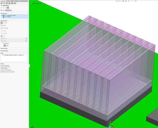
How to create a simple region quickly
- Create a new part and select one end of the heat sink as the initial sketch plane
- Sketch out the size of the region.
- You can snap the corners of the rectangle to the corners of the existing heat sink geometry.
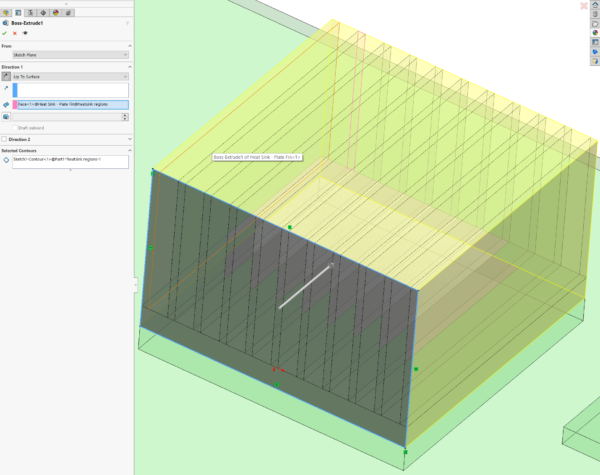
- Extrude the sketch to create the third dimension.
- If you don’t know what the length should be you can use one of the other options available like “up to surface” and select existing geometry to extrude up to.
- Save the part
- In Simcenter Flotherm XT tree set it to a region and it’s ready for use.
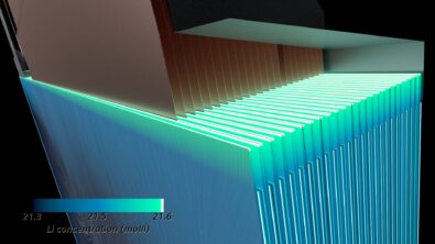
There may be times when I’m interested in analysing any difference in flow rate between the fins of the heat sink rather than the bulk flow through the whole thing.
In that case I have a couple of options. I could create separate parts between each fin and have several volumes.
Or I could have a single part but use sketch tools and split to create several different selectable faces.
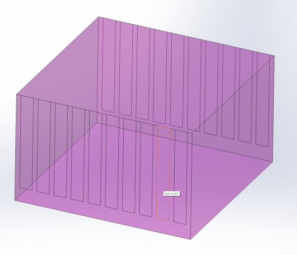
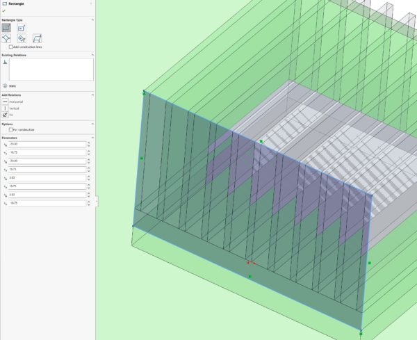
How to create a region with extra sketches for each channel
- Start with your single region as before but stay in editing mode once you’ve finished the extrude.
- Draw another sketch using the face abutting the end of the fins as the sketch plane.
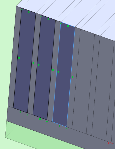
- On this sketch plane create several rectangles.
- You can use the fin geometry as before to align your vertices.
- Save and exit the sketch.
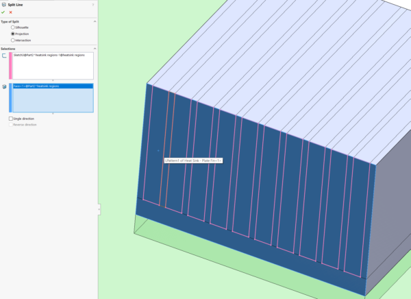
Split the faces of the region with the smaller sketches.
- On the features ribbon toolbar, select Curves > Split line.
- Select the projection option
- Use the sketch you just created and the surface of the region you want to split.
- You can select more than one face to split at once so you can split the entry and exit sides of your region at the same time.
- Save the part
- Don’t forget to set it as a region from the Simcenter Flotherm XT tree.
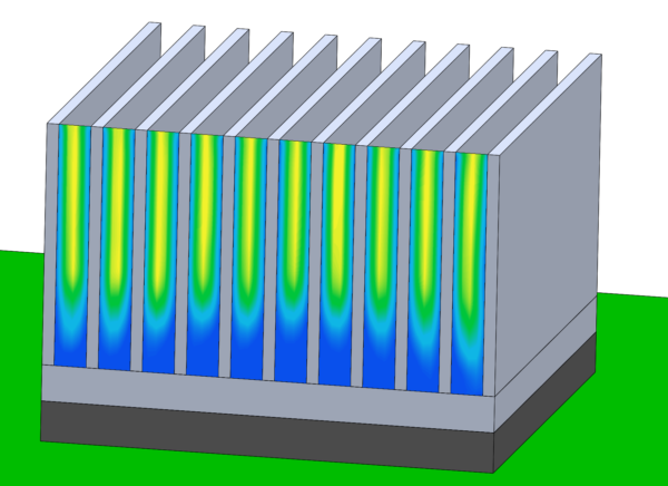
Now you have a region with multiple faces you can select for interrogation in post-processing.
How to use your region in post-processing
- Surface plots
- Visualise pressure or speed
- Surface data inspector
- Quantitative data
- Mass or volume flow rate
- Fluid temperature, velocity and pressure
- Goals
- Difference goal
- For pressure or temperature difference between two surfaces
- Use for a single slot, or over the whole entry/exit face.
- Set for convergence criteria or just monitoring
- Surface goal
- Temperatures (average and maximum)
- Pressure
- Velocity
- Mass flow rate
- Set for convergence criteria or just monitoring
- Difference goal
Regions can be useful when you want information on the fluid within and around solid geometry. Using the CAD geometry tools that come with Simcenter Flotherm XT can make regions more powerful.