The Thermal Benefits of Vapor Chambers
Vapor chambers are becoming an increasingly common thermal solution for electronic devices. They can be found in a range of systems, from mobile phones to high-powered laptops and video game consoles. In this blog we will discover what exactly is a vapor chamber; learn how to model them using Simcenter Flotherm XT; and analyse the thermal benefits of vapor chambers compared to traditional heat sinks.
What is a vapor chamber?
A typical vapor chamber consists of a hollow copper enclosure (the chamber) that is filled with a small amount of liquid water. This chamber is then vacuum sealed below atmospheric pressure; allowing the liquid water to evaporate (the vapor) at temperatures lower than 100 °C.
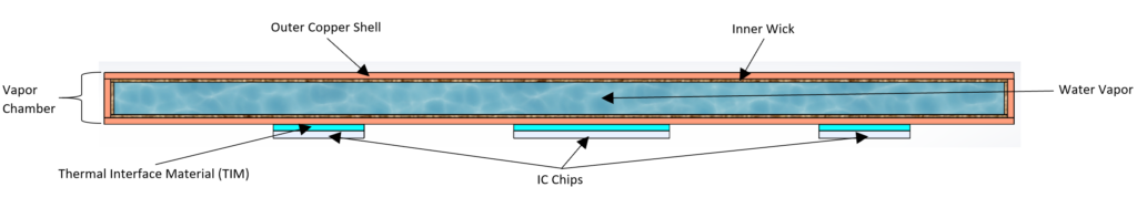
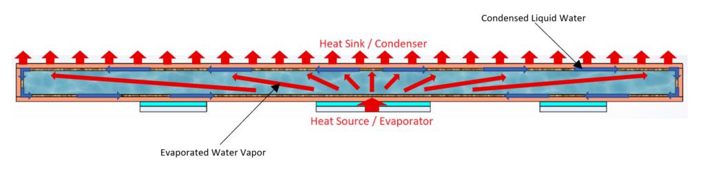
The working principle behind a vapor chamber is the same as a typical heat pipe. It relies on the evaporation and condensation cycle of the water to transfer heat from the hot side of the chamber to the cooler side. The inner wick then acts as a carrier for the condensed liquid water to flow back around to the evaporation side using capillary action. Then the cycle can begin again.
Vapor chambers can be used as a thermal cooling solution on their own to spread and dissipate heat. This is often seen in some mobile phones where space is limited. However, vapor chambers can also be attached to the base of a conventional heatsink when even greater cooling efficiency is required.
Is a vapor chamber better than heat pipes?
Although the operating cycle for both a vapor chamber and heat pipe are similar, the choice of cooling solution will depend on the application. For instance, vapor chambers are very effective at uniformly spreading heat laterally across a surface. In contrast, heat pipes are good at transferring heat from one place to another.
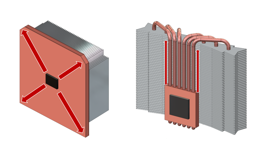
The flat shape of a vapor chamber also means they can make better surface contact with IC chips, or to the base of an attached heat sink, to create a more direct heat transfer path. This contrasts with the cylindrical shape of a heat pipe, which prevents it being directly attached to a component. Instead they require additional connecting parts or modifications before the heat can even reach the pipes.
Modern manufacturing can produce vapor chambers as thin as 2.5mm. This makes them very useful in compact electronic devices such as mobile phones or vapor chamber laptops. In addition, their thin shape means they are less affected by orientation, unlike a traditional heat pipe where the direction of gravity can affect its cooling efficiency.
In order to visualise the thermal benefits of vapor chambers, let’s use some CFD analysis with Simcenter Flotherm XT.
Modelling a vapor chamber
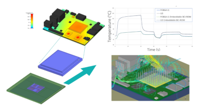
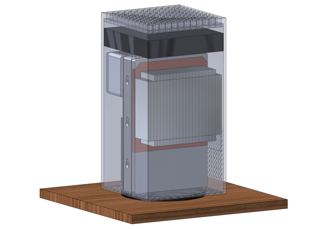
Let’s start by taking a typical model of a high-powered video game console. Most of the heat output is from the main System on a Chip (SoC) producing 100 watts of thermal power. We will compare the SoC temperatures with 2 different attached heat sinks: First a standard copper base heat sink, then with a vapor chamber base heat sink. Both will be of equal size and with aluminium plane fins attached.
Modelling a vapor chamber explicitly is not a straightforward endeavour. It requires a lot of computational time (and an engineer’s time) to model the evaporation and condensation cycle on which they operate. Because of this, it is often quicker and more convenient to create a simplified model, which will closely approximate our desired vapor chamber characteristics.
We will take our standard heat sink in the model above, and modify the copper base into a sandwich of solid conduction layers that represent the vapor chamber:
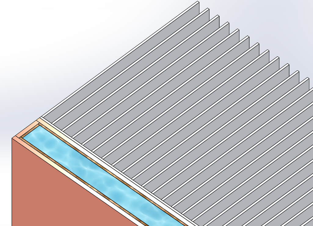
We can now apply effective thermal conductivities to the newly added wick and water vapor layers. We will use values that best approximate the vapor chamber in its operational state:
Wick = 40 W/(m K)
Water Vapor = 30 000 W/(m K)
You may notice the very high effective thermal conductivity of the water vapor. This gives us some insight into the type of cooling performance we can expect to see from our vapor chamber!
CFD analysis
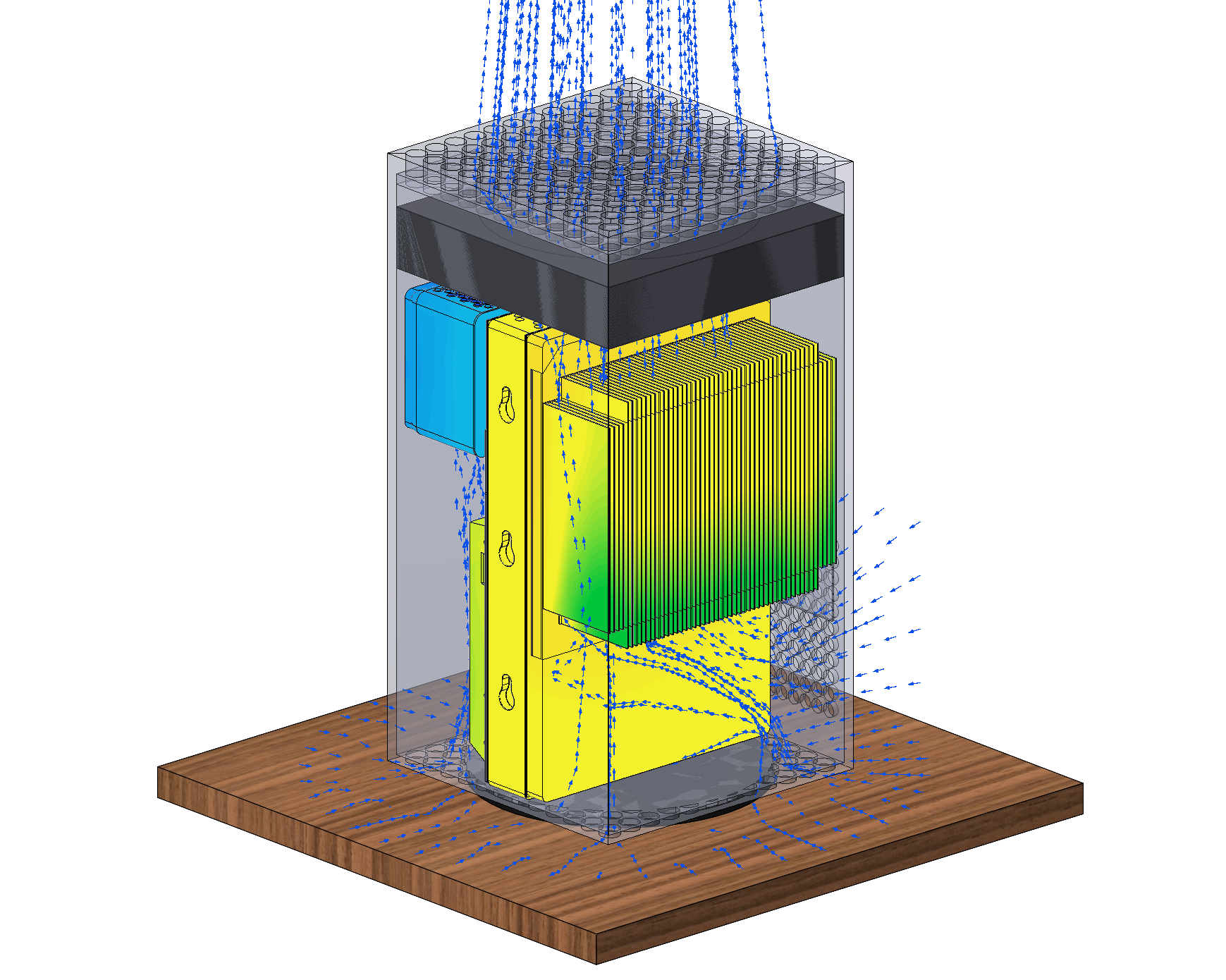
The model was first solved using the standard copper base heat sink. This was then followed by a second solve with the vapor chamber heat sink. The forced air flow pattern through the device can be seen below:
By generating a temperature plane plot on the vertical axis, we can take a look at the SoC temperatures using the standard copper base heat sink:
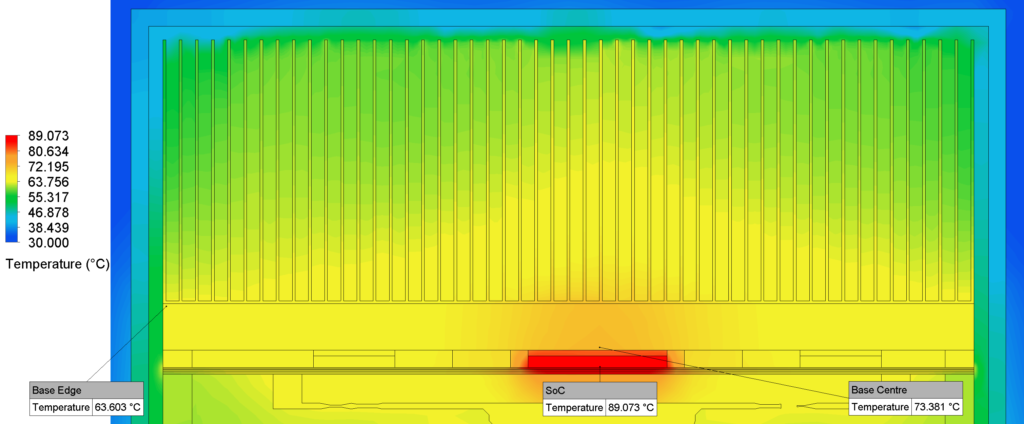
The SoC reaches a temperature of 89°C, with heat accumulation centred around the middle of the heat sink. Notice that a ΔT of 10°C occurs from the centre to the outer edge of the copper base. This shows that the heat is unable to effectively reach the outermost fins of the attached aluminium heat sink. Consequently, this results in an inefficient use of the surrounding air flowing between the aluminium fins.
Now let’s take a look at the SoC temperatures using the vapor chamber heat sink:
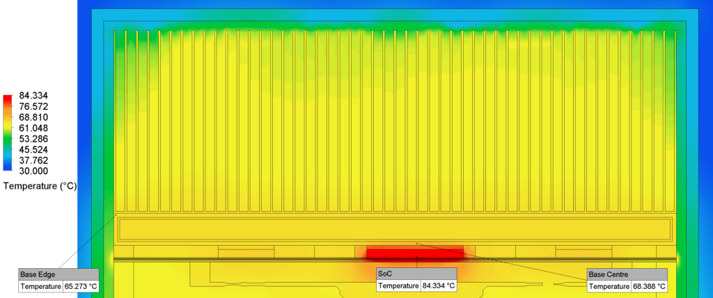
This plane plot reveals a 5°C drop in temperature for the SoC compared to that of the copper base heat sink, which is an excellent improvement! In addition, the vapor chamber exhibits a ΔT of just 3°C from the centre to the outer edge. This demonstrates a more uniform and improved lateral spreading of the SoC heat – a common benefit of using vapor chambers!
As a result of the improved lateral spreading, the vapor chamber has enabled the heat to flow more evenly across a higher portion of the attached aluminium heat sink fins. Consequently, this allows better utilisation of the total volume of air flowing across all the fins. This is in contrast to the copper base heat sink, which only effectively utilised the middle fins and central air flow.
Conclusion
Modern electronic devices require more advanced cooling technology than ever before, and vapor chambers can be an excellent thermal solution. Using Simcenter Flotherm XT, we have visually demonstrated the thermal benefits of vapor chambers; showing how they can offer improved cooling efficiency with better lateral heat spreading than a traditional heat sink of the same size.
Have you seen any other devices or different industries utilising vapor chambers as a thermal cooling solution? If so, we would love to hear about them in the comments section below!