Hydrogen usage with Simcenter System Simulation: Mobility and stationary applications – Part 3
This blog post is the Part 3 of a blog series for addressing the industrial Hydrogen challenges with Simcenter System Simulation. It’s focused on the Hydrogen utilization in Mobility and stationary applications. A quick overview is introduced in the previous Part 1 with explanations why Simulation is really appropriate to address the Hydrogen challenges. While another Part 2 shows various applications for hydrogen production, distribution and storage.
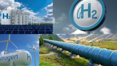
Hydrogen can be used for many applications including power generation, heating buildings and transportation. Because of its versatility, many countries have developed clean hydrogen production strategies and invested in its transport and usage. Let’s have a deeper look here to better understand the benefits of using System Simulation for the Hydrogen usage in Mobility (passenger cars, trucks, forklifts, excavators, airplanes, ships, railways, …) and stationary applications (hydrogen refueling stations, residentials, …). We’ll see how System Simulation is driving the digital transformation to tackle all your Hydrogen challenges.
Hydrogen Refueling Stations (HRS)
♻️💧⛽ We see more and more traction for our ready-to-use digital twins for Hydrogen Refueling Stations (HRS) with Simcenter Amesim. There’s actually a big gap between the nice images showing clean, perfect and seamless refueling stations and the reality with complex systems which are actually a bunch of multiple components (compressors, valves, tanks, …) combined with automation, advanced control logics and thermal management with heat exchangers. So the reality is complex challenges to manage practically to get efficient and cost-effective installations. Let’s see how our tools have all the appropriate capabilities to investigate many scenarios 📊 that run in few seconds ⏱️ thanks to System Simulation.
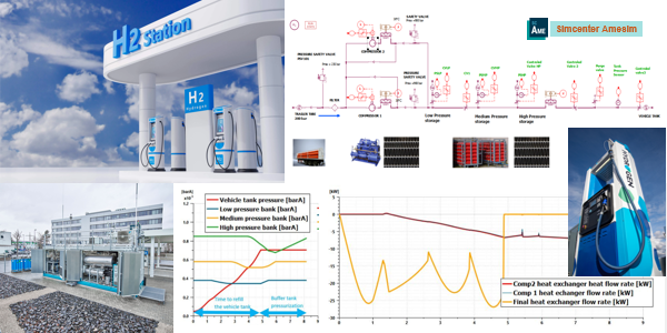
Practically, it’s related to tackle many design requirements, reason why System Simulation is needed here for:
📐 Sizing and performances
📚 All hydrogen components (valves, …), predefined and ready-to-use (no coding)
💧 Real gas at high pressure with the right Equations of State (EoS)
🌡️ Thermal management, cooling
🎛️ Control strategies with state machines (Statechart)
🔌 Connection to the PLCs (Inputs/Outputs) and Hardware devices
⚙️ Automation and Virtual Commissioning
⌛ Minimizing refueling time to few minutes (similar to fuels)
♻️ System efficiency (influence of compression, highest %)
💥 Safety, no risk of explosion (operators, …)
💰 Cost effective (CAPEX/OPEX)
Hydrogen storage systems for trucks
Compressed Hydrogen tanks can be seen as simple components like chamber volumes, but they are actually complex systems to manage. Especially during filling and defueling, there are huge evolutions in temperatures at various locations within the tank and all along the tank walls, that need to be controlled properly.
When several tanks are combined in series or in parallel, the challenges become even more complex. While the initial operating conditions (initial pressures, initial temperatures) are different in each tank, and the tank characteristics (length and diameter, horizontal/vertical layout, position of the valve at top or bottom, number of layers, types of materials, …) introduce many variabilities. Also considering that the weather conditions (external ambient temperature, solar irradiance, …), the fuel delivery (mass flow rates [kg/s]) and fueling protocols (“SAE J2601” for 35 MPa and 70 MPa, …) that bring additional inputs to manage the risks and to ensure safety for operators and drivers.
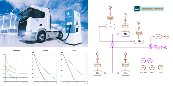
Typically, all the risks need to be assessed upfront, like a too low temperature during defueling or a too high temperature at the fuel cell side. While the complete system also includes the on-tank valve, the pressure regulator unit, various pipes at high or medium pressures and the cooling systems. Finally, the control logics must be refined to match the protocols and pass the certification.
Note that some new advanced approaches investigate MPC (Model Predictive Control) to forecast the temperature evolutions within the tank, being a dynamic prediction, rather than using the usual lookup table control methodology, which is static to not say empirical. The benefits of such MPC (Model Predictive Control) approaches will appear in the next generation of Hydrogen station dispensers with better refueling control strategies and drastically reduced refueling times. That’s another area where System Simulation can definitely help!
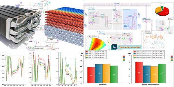
Fuel cell energetic performance
System simulation allows to represent a complete Fuel Cell Electric Vehicle within one single model to predict interactions between the vehicle powertrain, the fuel cell and its auxiliaries as well as the controls. So that you can investigate Fuel Cell Electric Vehicles such as the Toyota Mirai or the Hyundai Nexo. To be well predictive on the vehicle range, the vehicle energetic performance and the hydrogen consumption for realistic driving cycles. The models include the following subsystems:
- the vehicle environment and the electric motor,
- the electrical network and the battery,
- the fuel cell stack,
- the air supply system and its control at the cathode side,
- the hydrogen recirculation loop and its control at the anode side,
- the stack cooling system.
Practically, many aspects are considered like:
- the gas species in the mixtures, the gas properties,
- the liquid water properties and the water phase change conditions,
- the thermal properties of the solid part of the stack,
- the cooling system model data (coolant properties and ambient conditions).
Also for the electric circuit with:
- a 245V high-voltage bus where the High-Voltage (HV) battery powers the coolant pump.
- a 650V power-boost bus where the fuel cell stack, the air compressor and the traction motor are plugged in. A DC/DC converter links these 2 buses together.
- a 12V low-voltage bus where the Low-Voltage (LV) battery powers the radiator fan.
Note that regenerative braking, through the traction motor, is considered in the models. While the stack/battery control strategies can be modified in the fuel cell controllers.
The fuel cell stack evaluates the stack voltage considering the current, the temperature and the operating conditions at the cathode and the anode. The electrochemical equations are set so that the stack voltage can depend on the reactive species conditions at the electrodes. It also predicts the products and reactants’ molar flow rates due to the chemical reaction and it models water transport across the membrane.
The dynamic thermal behavior of the stack is predicted for the membrane and the bipolar plates. It results the balance between the heat generated by the fuel cell stack and the heat removed from the coolant loop. The traction motor power request drives the fuel cell stack operation through a DC/DC converter connected to the high voltage electrical circuit.
Finally the cooling system is used to regulate the stack temperature, with a pump to generate the coolant flow (water and glycol mixture) in the cooling loop. And when the coolant temperature rises above a specified threshold, the thermostat starts to open and it releases coolant into the radiator branch. A second threshold triggers the fan when additional cooling power is needed.
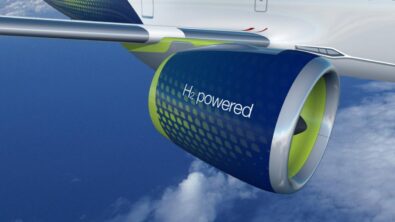
Aircraft hybridization with hydrogen-powered propulsion
The Hydrogen transformation also reaches the aerospace industry. Typically, it’s about aircraft hybridization with hydrogen-powered propulsion. Aerospace engineers face challenges that are directly part of the process of designing sustainable aircrafts. System Simulation drives the next-generation propulsion systems with a special focus on the early design stage, it investigates how to use hydrogen-powered jet engines and hydrogen fuel cell technology and their implications for subsystems, culminating in the need to reimagine aircraft configurations. With easy-to-create and quick-to-execute digital twins, System Simulation helps the aerospace engineering organizations optimize aircraft performance using virtual and physical testing of the fluid, thermal, mechanical and other system domains impacted by green aviation.
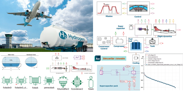
The list of topics to address practically is as large as all these subsystems with their associated requirements and assessments. It’s also multi-attribute balancing to find out the best architectures, configurations and sizing to reach the best design. It includes:
- Fuel cell aircraft concept
- Propulsion system
- Propeller
- Flight mission
- Aerodynamics
- Fuel cell stack
- Fuel cell balance of plants
- Cryogenic tank
- Ultracapacitors pack
- Hydrogen combustion concept
Using Simcenter Amesim and its various libraries and available apps enables you to model the various subparts of an aircraft quickly and accurately, such as propellers, fuel cells or turboprops and test their integration into a complete aircraft model. Regarding the results, hydrogen-burning turbo-propellers look like the most viable and quickest solution to reduce the aerospace carbon footprint. The adaptation of the system would be easier and the impact on total aircraft weight would be negligible regarding standard architecture. But to reach zero emissions, fuel cell propulsion architecture is a promising alternative with much more optimal energy usage delivered by hydrogen as a fuel. System Simulation can help to identify the fuel cell limiting factors, such as hydrogen storage and distribution, which lead to payload reduction. Also to improve the ultracapacitors’ specific energy and fuel cells system’s specific power to reach viable designs.
Hydrogen burning turbofan
System Simulation is well suitable for gas turbine design and power generation. Driven by the changing needs of the energy market, gas turbines must become more efficient and reliable while working under new flexible operating patterns. We now see Hydrogen appearing for gas turbines, so users need to explore the turbine performance digitally, to reduce expensive testing time and gain confidence in their products early in the design cycles. At the same time, to stay competitive, turbines must become cheaper to manufacture and operate.
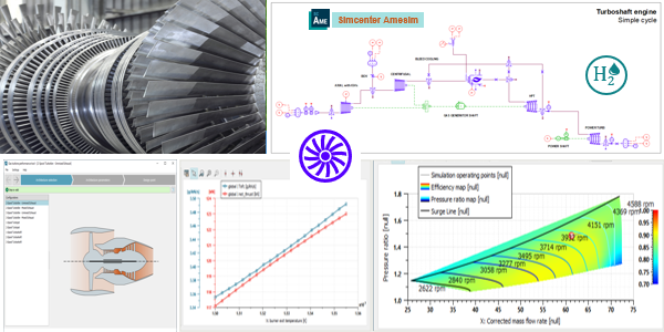
In the zero-carbon emission perspective for gas turbines and aero engines, the hydrogen-propelled regional aircrafts need a preliminary design and that’s where System Simulation can definitely help, from hydrogen combustion up to the complete system integration to understand the performance of the complete turbine system. While it can be used over a wide range of turbine applications, including primary airflow, secondary airflow systems, fuel and auxiliary systems, whole engine modeling with combustion, and control validation.
Space LH2/LOx cryogenic rocket engine
It’s actually a very long time (many years) that we’ve been successfully representing the liquid hydrogen (LH2) used for space LH2/LOx cryogenic rocket engines with System Simulation. 💻📋📊 The digital twin comes with an integrated framework for mission analysis 🔭🪐 and the impact of cooling jacket temperature 🔥🌡️ on engine start-up 💥📈.
The RL10A-3-3A is a rocket engine used for the upper stage vehicles. It was developed by Pratt & Whitney, under contract to NASA (“National Aeronautics and Space Administration”, started in 1958, as a part of the United States government). The RL10 engine is based on an expander cycle using liquid hydrogen (LH2) and liquid oxygen (LOx). In an expander cycle, the heat dissipated by the combustion chamber is used to gasify and raise the gas temperature of the hydrogen. In this way, it can be used to drive the turbine, which in turn drives a single-stage liquid oxygen pump (through a gear case) and a two-stage liquid hydrogen pump, before being injected into the combustion chamber and burned. Finally, the products of the combustion are accelerated in the rocket nozzle to generate thrust.
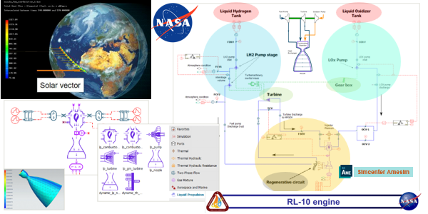
The RL10A-3-3A engine is modeled using the Liquid Propulsion library in Simcenter Amesim software. The Liquid Propulsion library consists of a set of specific components for cryogenic engines as pump, turbine, combustion chamber and nozzle. This library is an extension of the Two-Phase Flow and Gas Mixture libraries, which addresses the physical phenomena linked to dynamic gas mixture, combustion and phase change transition (supercritical, boiling, condensation…). Components from other libraries such as shafts, accounting for mechanical dynamics, gearboxes, electrical generators, heat exchangers can be combined with this library components to allow the modelling of any rocket engine configuration and any integrated systems.
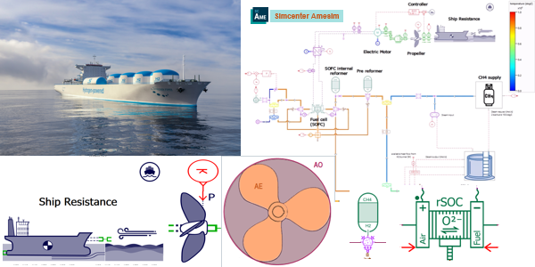
Marine SOFC propulsion cargo ship
The Marine industry can also benefit from the System Simulation capabilities to address the Hydrogen challenges. Typically, it could be the integration of a Solid Oxide Fuel Cell (SOFC) with a methane reformer to power a cargo ship. It’s well predictive 📊 to get all the info related to the trip (sea routes, …), CO2, CH4 and its global efficiency. So it’s easy to size 📐 and optimize your ship design 🎯 in a few clicks, with simulations of the complete sea route executed in few seconds ⏱️.
Solid Oxide Fuel Cells (SOFCs) and Natural Gas or methane (CH4) reformers can be used in ships to provide an efficient and clean power generation system. It comes with challenges, including cost considerations, infrastructure requirements, and technological advancements.
Practically, System Simulation helps address all the requirements, which is crucial for such new innovative systems where the usual stakeholders miss knowledge and past experiences to design the best system at first. It’s related to various design requirements like:
🚢 Fuel cell system integration for ships
🌊 Ship propulsion system and resistance model
⚗️ CH4 reformer and Hydrogen supply system
⚡ High temperature fuel cell (SOFC)
💦 Water management
🌡️ Thermal integration
The sea route can be defined according to a specific trip from Point A (let’ say Oslo in Norway) to Point B (let’s say Le Havre in France). Sailing conditions are defined as well as the ship characteristics (type of boats, shape, weigh, length and width, …) and the time required to perform the trip. So you can also get predictive results at the end of the simulation like:
– Trip distance: 700 nmi
– Trip duration: 330564 s (3 days, 19 hours, 49 minutes and 24 seconds)
– CH4 consumption: 6.13 t
– CH4 consumption per nautical mile: 8.77 kg/nmi
– CO2 emissions: 15.1 t
– CO2 emissions per nautical mile: 21.6 kg/nmi
– Global system efficiency (from CH4 tank to propeller, based on CH4 HHV): 42%”
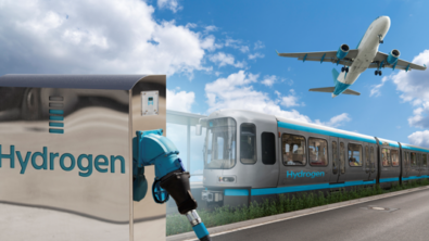
Railways with fuel cell propulsion for trains
In the Railways industry, it’s the same approach used with System Simulation to address the Hydrogen challenges. It’s about the decarbonization of railway transportation, with the replacement of diesel trains by electrified ones. With some additional railways specificities (mission velocity profiles, acceleration / deceleration, traction and resistance, bogies/rails contact and friction, …) and constraints (auxiliary systems like HVAC / air-conditioning that consumes energy, regenerative braking, …). Also considering some switches in the operating conditions for the regional train performing not only as an electric train for routes with overhead power lines, but also as hydrogen and battery-powered variants. The use of fuel cells (so hydrogen) is needed when the lines are not connected to the grid.
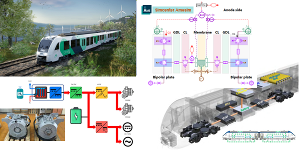
It starts with the fuel cell and its high-power density, while the hydrogen tank also needs to be optimized. Its absorption capacity can be increased by 10 percent, thus bolstering its long-range credentials. The hybrid control software optimizes operation through predictive energy management. And the family of powerful batteries boasts a long lifespan. Together, the new components make such hybrid trains suitable for deployments up to 1,000 km.
It’s finally a mechatronics system to be sized properly considering its dynamic behavior, it includes the fuel cell model scalability and the prediction of the fuel cell ageing and the impact of flooding. Finally, users get a better integration of the fuel cell stack with its Balance of Plant (BoP), reaching nice achievements of the best reliability and life expectancy, with some considerations of ageing in the control design. That’s really impressive, isn’t it?
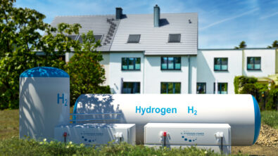
Residential SOFC micro-combined heat and power
🏠♻️💰 For Residentials, so smart houses / smart buildings combined with energy management and advanced controls, System Simulation also shows nice contributions for modeling innovative hydrogen applications 💧like the Residential SOFC micro-combined heat and power (m-CHP). System Simulation helps find out the best solutions among dozens of possible configurations ⚡✅, while the energy price and associated strategies change depending on the countries. Considering some economical aspects and the best strategies to use depending on the countries (here France or Germany, but it could be any other country worldwide) that have different energy mix. Which greatly impacts the total energy cost and equivalent CO2 emissions.
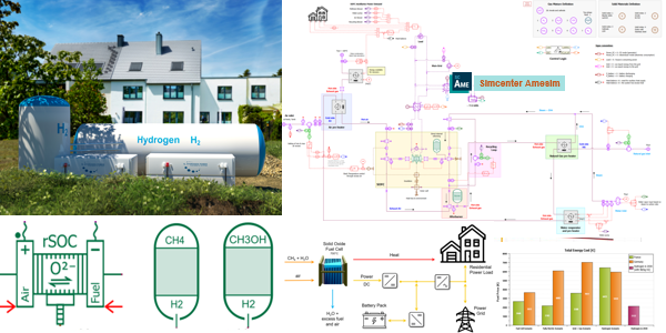
System Simulation with Simcenter Amesim can represent the complete balance of plant (BoP) of the SOFC (Solid Oxide Fuel Cell) fueled by natural gas and applied to a residential house, with a sensitivity analysis of some of the most important inputs to the system. It goes up to considering the other ways of supplying the household demand, such as using only the electricity grid, a combination of power grid and natural gas, or hydrogen only.
In details, System Simulation helps represent:
💧The digital twin including the SOFC, reformers, battery pack, grid, controls, …
📊 With some economical aspects / energy price (€) or CO2 emissions (kg)
🌎 Also considering the strategies depending on the countries, like Germany or France
💰 To show that a relevant strategy in one country may be different for another country
⏱️ The run execution for 1 year (365 days) takes only few minutes
The outcomes are very clear that with the emergence of hydrogen as an alternative clean fuel, the Solid Oxide Fuel Cell (SOFC) is seen as a promising power generation technology, especially for residential applications that are already connected to the natural gas network. What a great conclusion!
Summary
In summary, embracing hydrogen in product development requires a strategic approach, early-stage considerations, and advanced tools like physics-based digital twins to navigate the complexities and leverage hydrogen as a competitive advantage. Hopefully you got a first flavor of the thousands of possibilities whatever the industries and applications from this overview of typical the Hydrogen usage for mobility and stationary systems.
If you’ve missed it, please read the Part 1 and Part 2 of this blog series to get a general overview how System Simulation helps being successful in your Hydrogen journey thanks to digitalization.
Learn more about Siemens Simcenter Amesim
Simcenter Amesim is the leading integrated, scalable system simulation platform, allowing system simulation engineers to virtually assess and optimize the performance of mechatronic systems.