Digital twins – successfully combining simulation and test
Vehicle electrification is accelerating, with increasing pressure on the vehicle development time. New players are entering the market, and existing OEMs cannot afford to miss out on new opportunities or waste time during development. Hot topics like digital twins and front-loading of NVH design are intriguing areas of discussion.
However, Electric Vehicle (EV) design faces numerous challenges. Specifically, when focusing on NVH (Noise Vibration and Harshness) challenges, they include:
- High-frequency tonal electric engine noise related to electromagnetic forces and gear whine.
- Tire noise, which is the primary noise contributor for electric vehicles.
- Wind noise due to turbulence on the vehicle outer surface.
- Much more audible auxiliary noises, due to the absence of broadband ICE (Internal Combustion Engine) broadband noise coverage.
Front-loading vehicle development
To tackle those challenges efficiently, automotive development needs to detect and address as early as possible NVH issues during vehicle design. However, fully assembling the vehicle is only possible late in the design phase, which means that efficient troubleshooting becomes crucial at that stage. If you are at this point, you might want to explore our Simcenter Transfer Path Analysis (TPA) capabilities, which offer the most efficient troubleshooting approach in the market. But let’s wait and see what comes next.
To effectively address issues in the early vehicle design stages, we need to front-load vehicle-level NVH design. But what data should be used? The available data includes historical data from tests and simulations. As vehicle development progresses, new test or simulation data becomes available. To succeed in front-loading vehicle-level NVH design, it is necessary to combine simulation and test data, resulting in a vehicle model known as the digital twin of the real vehicle. The digital twin follows the real vehicle throughout the entire development process.
Virtual Prototype Assembly for digital twins
Simcenter Virtual Prototype Assembly (VPA) can do exactly that. VPA is using component models and assembles them virtually. The C-TPA (Component-based TPA) methodology inside VPA makes it possible to use component data for the assembly. With FBS (Frequency Based Substructuring) the different parts are assembled together and coupling effects are considered.
Inside Virtual Prototype Assembly
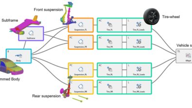
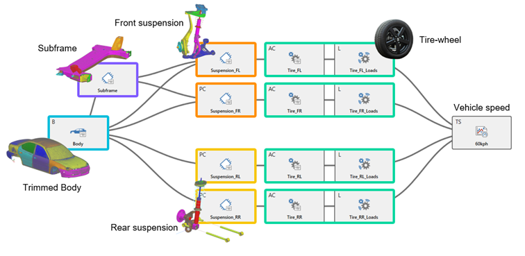
The components inside VPA can be active components – the noise sources, such as wheels, electric powertrains, and auxiliary devices in the vehicle. Passive components can be the suspensions, subframe, or the trimmed body itself. As a side note, VPA can be used as well for pass-by noise using thus transfer functions from the source to the pass-by noise microphone. In most cases, VPA is used for interior noise predictions, based on measured or simulated transfer functions to the inside of the vehicle. The image below shows an example of such an assembly.
With our Simcenter Testing solutions, one can naturally acquire all necessary test data. But VPA supports a large variety of simulation results in the same way. Those can be visualized, but even more important, those data can be published inside Simcenter Testlab into a VPA component. The supported simulation data can come from different simulation software companies, such as Ansys, Hexagon, Altair or Simcenter 3D.
How to combine two worlds – test and CAE?
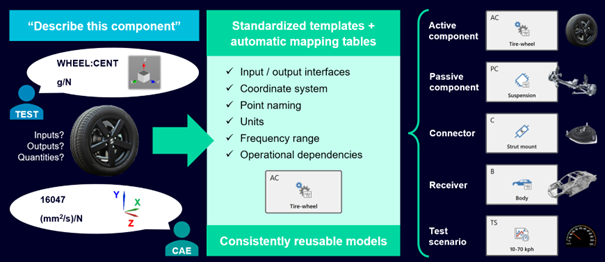
The answer is to build a standardized component library based on templates. Indeed, if each component of VPA is built based on the same template, everything will fit into each other like pieces of a puzzle. This is exactly how we build our VPA model, based on building blocks created with templates. Out of each input, we make a standardized component. Inside such a component we are taking into account the input/output interfaces, coordinate system, point naming, units, frequency range, and operational dependencies.
Unit system and point mapping
Of course, there is still a lot more to share, but let us focus on the CAE data support. Here we want to show one additional capability of VPA. When connecting simulation and test data, one must take care of two very important points:
- the unit system compatibility (below the dedicated lookup table) and
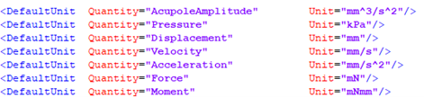
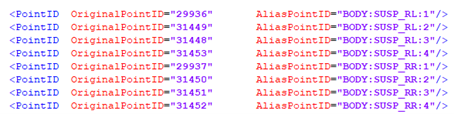
- the correct connections of simulation nodes with test sensors/impact points (below, dedicated lookup table)
Many simulation software result files don’t contain unit systems, or those are annotated in a particular way. Therefore, the software, here Simcenter Testlab that reads the data needs to be able to assign and convert units.
Both lookup tables are easily accessible inside Simcenter Testlab. This is completely compliant with OEM methodologies, where important nodes have the same node numbers. The effort required to set up such a mapping table easily pays itself back. Consider the road noise case we use below: CAE component models easily contain thousands of FRFs that are all mapped to standardized naming conventions without any manual input!
Components inside VPA based on simulation data
Thanks to the above look-up tables, it is very easy to open simulation data and publish them through Simcenter Testlab. Here is a video example of how fast component publishing can be. In this example, the passive component of a front suspension is created.
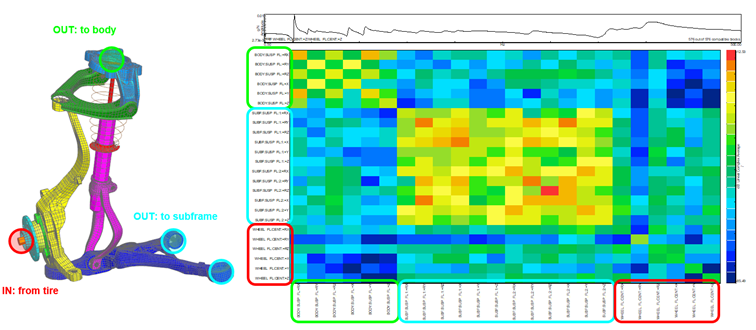
Let us take a look at two examples. Each component contains input and output nodes. Parts can be connected to various other passive components or lead to target indicators.
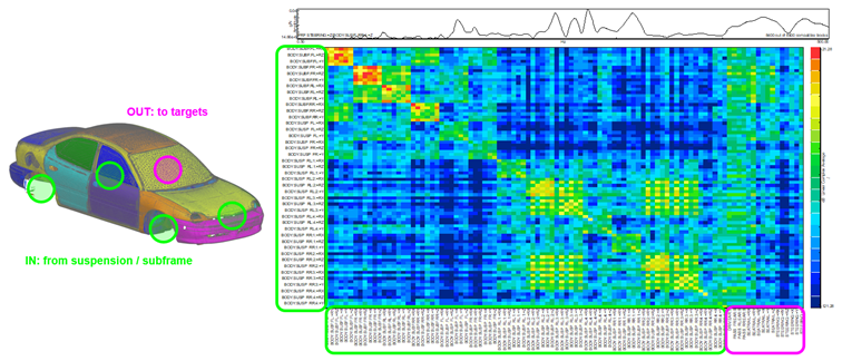
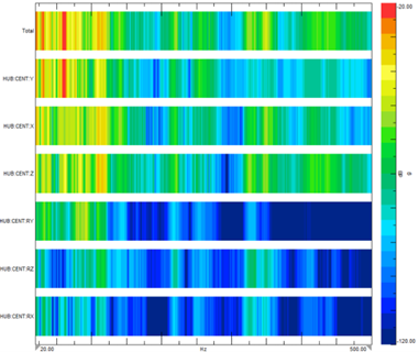
The heatmap in the below images shows the average driving point admittance and Frequency Response Functions (FRF) of different connections. Higher off-diagonal levels of the admittance entries indicate cross-coupling. Cross-coupling is visible in the front and rear suspension attachment zones of the trimmed body, or the subframe connections.
Passive component – front suspension
Receiver – trimmed body
Finally, the digital twin
Once the vehicle is assembled, we will apply a driving scenario, such as speed, RPM, and torque, depending on our source characteristics. Our digital twin allows making noise and vibration prediction and TPA analysis for any possible component/body/active component combination in VPA. We can look at contribution displays, visualized for the different noise paths structure-borne and airborne, or auralize the results and listen to them. Below is an example of steering column vibrations due to tire/road interactions.
All this is only a part of the full capability of our digital twin.
Contact us
Are you curious to see more, or do you have any questions? Please contact us.
Check out the following links for more information:
Virtual prototype assembly (VPA) for NVH prediction: from capability to process
System NVH performance prediction
Simcenter Testlab 2206: Virtual Prototype Assembly (VPA)
Transfer path analysis – a guideline to qualifying and quantifying vibro-acoustic transfer paths


