Fill/Cut Self-Aligned Double-Patterning
By David Abercrombie, Rehab Ali, Ahmed Hamed-Fatehy, and Shetha Nolke
How the SID-SADP process affects your design decisions –

Self-aligned double patterning (SADP) is an alternative double-patterning process to the traditional litho-etch-litho-etch (LELE) approach used in most advanced production nodes. The main difference between the two approaches is that in LELE, the layout is divided between two masks, and the second mask is aligned with respect to the first during manufacturing, while SADP generates the pitch (mask) split using spacers that are self-aligned to the first litho-etch step. The second mask in an SADP process is a block or cut mask used to trim the tips of the lines created in the first step and/or remove dummy lines. As a result, the SADP approach produces less variation due to mask misalignment (Figure 1).

Figure 1. Comparison of process control between LELE DP and SADP.
There are two general SADP approaches: spacer is dielectric (SID) and spacer is mask (SIM). For details of the fabrication steps in these SADP processes, you can refer to earlier articles in this blog [1][2]. Because most foundries currently prefer the SID approach for a metal interconnection layer, we’re going to explore the use of the SID-SADP process.
There are two main approaches in the SID-SADP process. The first technique uses a mandrel mask and a block mask. The mandrel mask contains some of the target lines, while the block mask protects all the spaces between metal targets with dielectric. This approach results in a complex block mask that may be very difficult to print [1][2]. The second approach is the fill/cut approach, in which a mandrel fill is applied by extending all target lines to the borders, with some additional dummy lines added to preserve sidewall widths. The second mask is the cut mask, which is used to create gaps in the lines to define the functional segments of the lines. While significant dummy metal is added to the original design in this approach, it is not electrically connected, so the capacitance impact is minimal [3].
The mandrel fill and cut mask of the second approach are more lithographically friendly, and easier to print in comparison to the mandrel/block approach [2]. One of the main challenges of the fill/cut approach is that the spacing constraints between cut shapes add constraints to the router. Sliding cuts can work as a solution to relax these constraints, but their use results in target extensions that add capacitance to the net. Generally, however, the impact of this additional capacitance can be minimized so as not to affect the overall circuit performance [2][3].
This unique type of layout decomposition introduces a whole new set of challenges to the custom and place-and-route design implementation and checking flow. Although design implementation tools may be able to address some basic aspects and constraints of this type of multi-patterning, as seen with even basic LELE-type decomposition, these tools can have significant limitations that lead to a large number of errors. It is critical to use verification tools that can not only check the full gambit of constraints, but can also provide efficient error visualization, comprehensive layout decomposition, and even some automated error fixing.
Fill/Cut SADP decomposition
To simplify the decomposition of a design when using the fill/cut SADP technique, all target shapes are assumbed to be unidirectional rectangles (limited 2D shapes are allowed in SADP under significant constraints—we’ll discuss those later). Moreover, all target shapes on the same track must be perfectly aligned with respect to each other, and must have the same width (Figure 2). The minimum target/track width is defined by the foundry, based on the printing limitation at the selected node.

Figure 2. SADP-compliant target design.
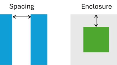
As discussed in previous articles [1][2], the target rectangles are accommodated by mandrel and non-mandrel tracks that have spacing constraints between each other, defined by the sidewall width. The target shapes have spacing constraints between each other in the preferred orientation, defined by the minimum area constraints and the cut shape dimensions (these cuts are used to create gaps between target shapes in the same track), as well as spacing constraints between each other in the non-preferred orientation, as defined by the sidewall width.
In the fill/cut approach, all target shapes are extended to the borders of the region being decomposed to form the occupied tracks (Figure 3). If there is a large space between target shapes in the non-preferred orientation, such as the one in the middle of Figure 2, this space is filled with dummy tracks to maintain the constant sidewall width. To be able to add dummy tracks at this space, the space between target shapes must be exactly equal to the sidewall width, or must be a multiple integer of track width + 2(sidewall width). In addition, if there is a space between the first or last target shape and the border, this space is also filled with dummy tracks. Usually, the first and last dummy tracks inside the border have a width that is larger than the minimum track width. Those specific dummy tracks are called terminal dummy tracks, as they are used to define the edge of the SADP area. Half of the tracks are then assigned to the mandrel mask, and the other half are defined as non-mandrel tracks.
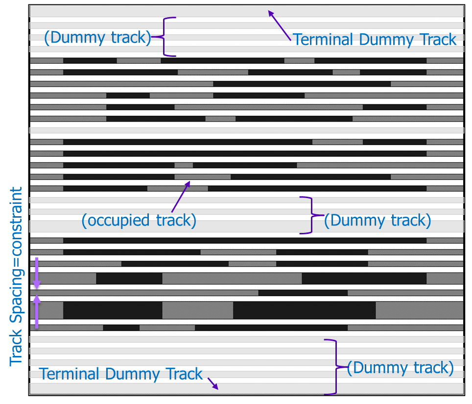
Figure 3. Occupied tracks and dummy tracks.
The “magic” of the fill/cut SID SADP process is the ability to easily create these self-aligned parallel tracks. The more difficult part is defining the line-ends of the targets on the occupied tracks. We need an etch stop at each line end to block the etching process at these locations. This etch stop mask is referred to as the “block mask” by some foundries (because it blocks etching at line-ends), while others call it a “cut mask” (because it cuts through tracks to define line-ends). Both naming conventions refer to the same thing. Because the etch stop is placed as a rectangle at the end of a line, and we typically refer to this rectangle as a “cut,” we’ll call the etch stop mask the cut mask. Figure 4 illustrates cut placements at the target line-ends.
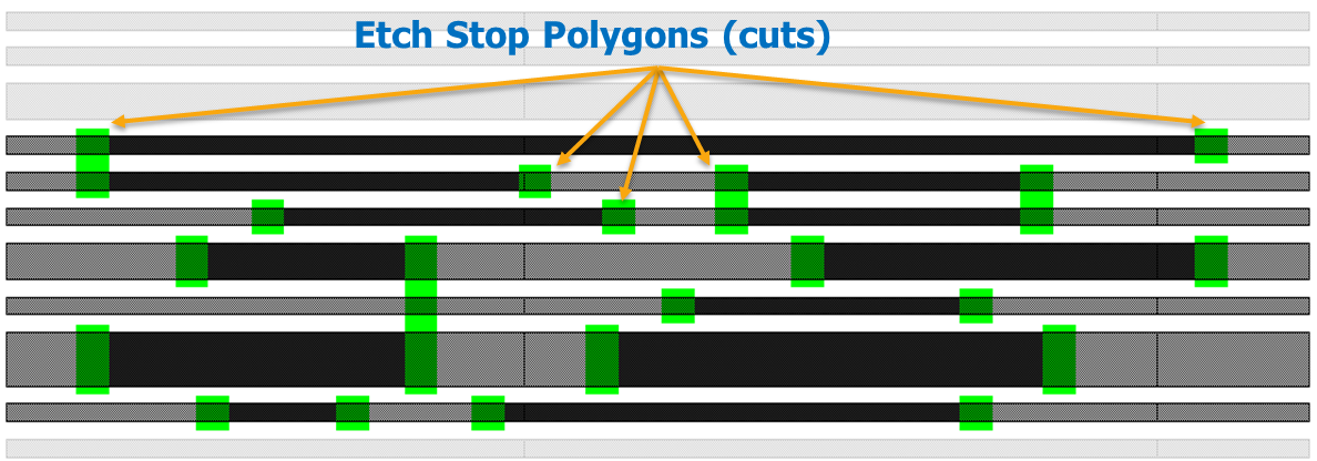
Figure 4. Cut placements at target line-ends.
In the simplest case, you generate the cut mask by placing a rectangle at the end of each target line. The length of this rectangle is based on the width of the track it will cut. As a result, the cut mask contains a variety of different size rectangles. Cut placements at line-ends automatically correlate the line-end to line-end spacing into a cut-to-cut spacing. However, this lateral spacing constraint is not the only existing constraint between the cuts of different sizes. The cut mask is very similar to traditional contact masks, where there are constraints on the contact’s dimensions and different spacing constraints between different contacts. With cut mask shapes, there are different spacing constraints between cuts, based on the size of the cut and its location relative to other neighboring cuts.
Place and route tools don’t actually understand cuts, however. They operate based on line alignment and staggering rules. When adjacent track line ends are aligned, a single long rectangle can be placed across both line ends to define the two cuts. This concept is typically referred to as cut merging. To avoid minimum spacing violations between the two cuts, they are merged into a single long cut. If the line-ends are not aligned, then cut merging is not possible, because it would produce non-rectangular cuts with tiny jogs, defined by the difference in the line-ends’ locations.
In addition, cuts cannot be merged across an endless number of tracks into very tall narrow shapes, as these shapes would be very difficult to print using a via/contact type process. In other words, there is a limitation on the maximum length of a cut, related to cut size and the aspect ratio between cut length and width.
Electronic design automation (EDA) multi-patterning (MP) functionality, like that found in the Calibre Multi-Patterning tool, can generate the tracks for the designer, using different styles. For example, the designer can determine the minimum allowed width of the generated tracks, and the tool will generate tracks with widths equal to or larger than this minimum width (dummy tracks with a width larger than the minimum track width can be used to preserve constant spacing between tracks, as illustrated by the wide dummy track in the middle of Figure 3). Another style of track generation defines a specific set of track widths, and the tool chooses from these discrete widths to generate the tracks. In some advanced cases, the designer can also define the sequence of track widths generated by the tool.
Fill/Cut SADP error debug
The Calibre Multi-Patterning tool also helps designers debug their SADP designs. The tool can easily detect target shapes that violate spacing constraints between each other, as well as target shapes with different widths or misalignment with respect to other targets on the same track (Figure 5).
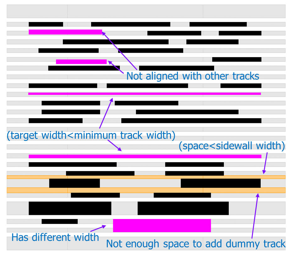
Figure 5. Different types of illegal target shapes and spacings that violate SADP constraints.
As long as half of the tracks are assigned to the mandrel tracks, and the other half assigned to the non-mandrel tracks, the designer can force some target shapes to be assigned to the mandrel or non-mandrel tracks. The Calibre Multi-Patterning tool can not only help the designer anchor the target shapes to the mandrel or non-mandrel tracks, but also detect any anchor conflict between tracks or between target shapes in the same track, as shown in Figure 6.
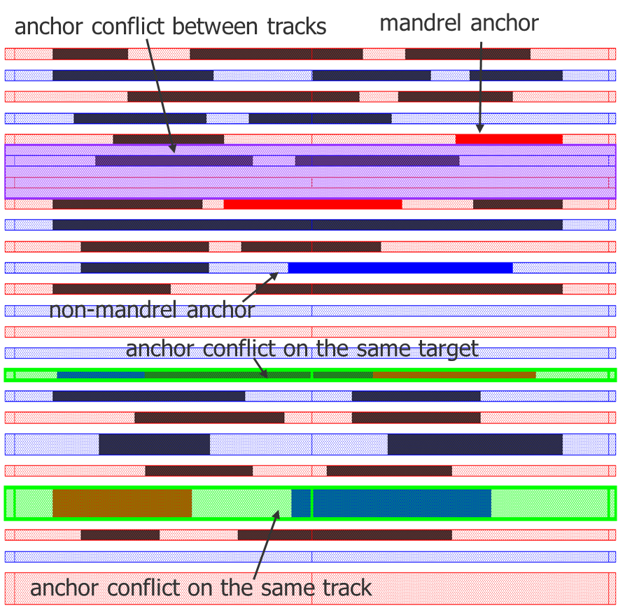
Figure 6. Different types of anchor conflicts.
When it comes to the cut mask, the main concern is satisfying the rules imposed on the cut mask. Cut merging across tracks is a simple way to avoid spacing constraint between small size cuts, but what about the case where we don’t have perfectly aligned line-ends? In these cases, it is possible to slide the cuts to maintain alignment and facilitate merging. This could be across multiple tracks and from both sides of the cut such as illustrated in Figure 7.
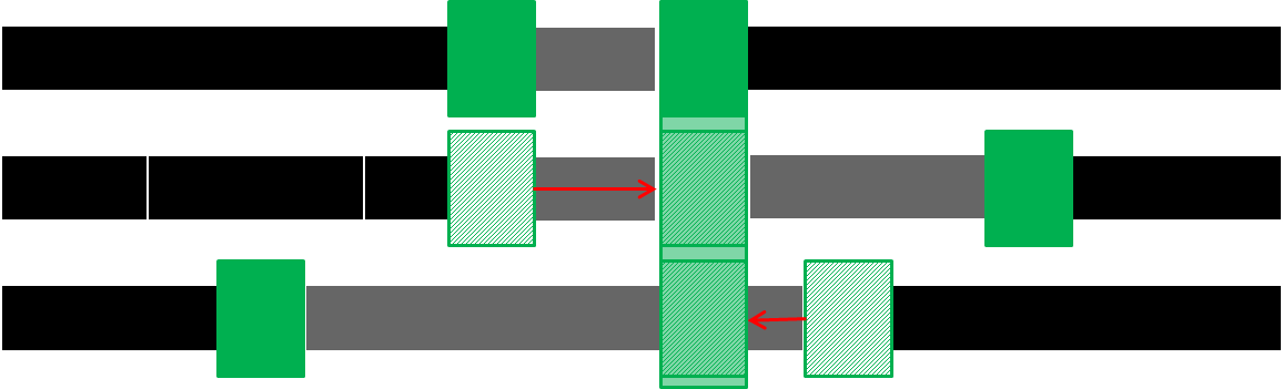
Figure 7. Sliding cuts for the sake of merging cuts.
An obvious side effect to cut sliding is that the final target line on the wafer will be longer than originally drawn, which increases the capacitance of the net. It is important to characterize the change in parasitic capacitances due to cut sliding, even though the impact is typically minor. The Calibre Multi-Patterning tool supports the ability to limit the maximum line-end extension used to resolve cut issues to help control these types of impacts.
Another restriction on cut sliding is that the sliding should not increase spacing violation between merged cuts and neighbor cuts. However, cut sliding can actually be used to avoid violating spacing rules between cuts. For example, in Figure 8, there is a spacing violation between the cut in the middle and its two neighbor cuts. The middle cut can slide to the right to eliminate this spacing constraint violation, as long as the slide does not create a new spacing violation with the long cut on the right.
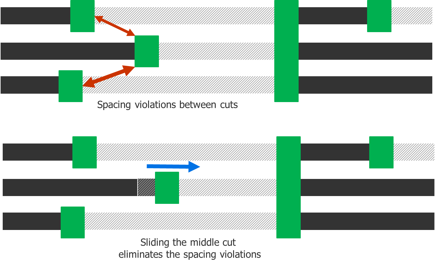
Figure 8. Cut sliding to remove spacing violations between cuts.
Occasionally, there may be a gap in between two targets’ line-ends that is not wide enough to allow a cut at each of the line-ends with a valid spacing between the two cuts. In this case, it is possible to drop one of the two cuts, and place only one cut extending one or both of the line-ends (Figure 9).
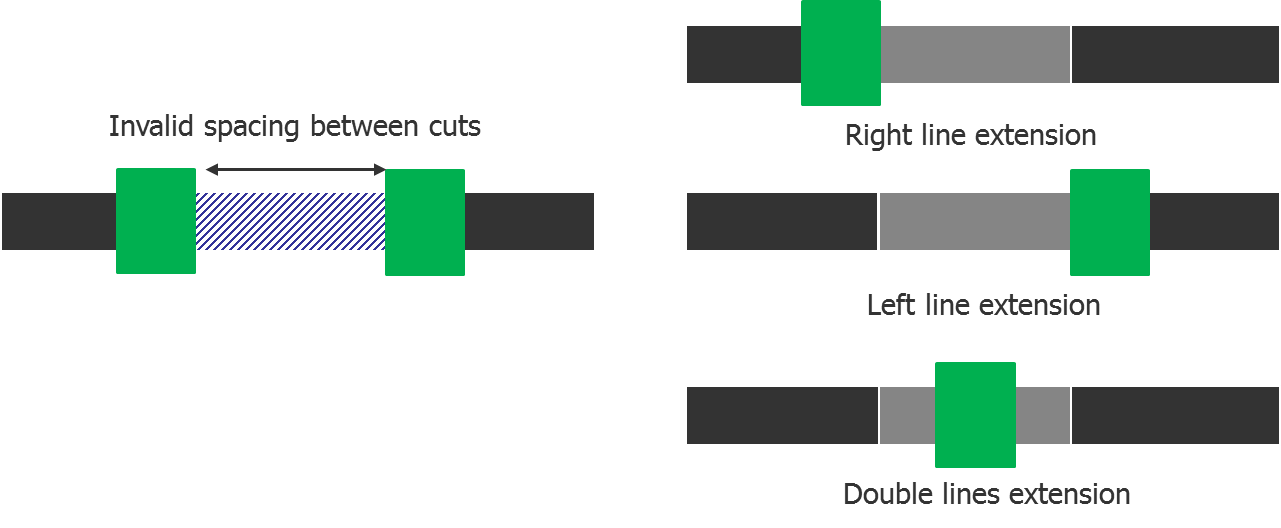
Figure 9. Different options for dropping a cut.
Different combinations of cut sliding, cut merging, and cut dropping can be used to comply with a variety of different cut mask rules, such as spacing constraints between cuts, and maximum allowable cut length. However, designers must be aware that using any of these solutions imposes further complexity on cut mask generation.
Alternative cut printing processes
When considering the mandrel fill/cut mask approach to SID SADP decomposition at smaller and smaller nodes, it may become necessary to consider alternative cut printing processes to achieve tighter cut mask pitch while remaining compliant with the process capabilities. While there will always be a single mandrel mask, these alternatives may use two or more cut masks for a single layer decomposition. Although the expense and complexity increase for these solutions, the benefit is the ability to achieve a tighter pitch design while still meeting the manufacturing process limitations.
One alternative method for achieving a cut mask configuration that meets the smaller cut to cut spacing is to use traditional LELE double (or more) pattern decomposition on the cut mask shapes. Once the cuts have been defined, a subsequent decomposition can be run to split the cut mask shapes into two (or more) colors. This allows the cuts to have a higher density without requiring an upgrade to the lithography methodology. Depending on the technology node, this methodology could be extended into three or even four cut masks. While the increase of cut density is useful for achieving a more complex design, it comes with the trade-off of overlay-induced error.
Another option to consider is a cut strategy that aligns to the coloring of the tracks upon which the wires are being constructed. This is commonly referred to as “selective etching” cuts [4]. With this process, the two colors of tracks are created with two separate materials that have different etch properties. This approach separates cuts into two colors, based on which tracks will be cut (Figure 11). Essentially, cuts are divided into those that cut mandrel tracks, and those that cut non-mandrel tracks. The secret to the success of selective etching cuts is that the mandrel tracks can interfere with non-mandrel cuts and not be affected by them, and vice versa for the non-mandrel tracks and mandrel cuts. This enables the cut shapes to span the unaffected tracks, making the cut shapes easier to resolve. While there is some concern associated with overlay alignment, this method benefits from having a more stable cut mask solution that creates less edge placement error in the final solution.
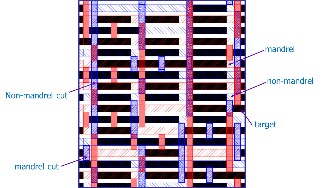
Figure 10. Selective cuts
While SID-SADP is certainly a complex process, and completely different conceptually from LELE MP, understanding its requirements and challenges and developing best practices for its use are essential for designers working at leading-edge nodes. Part of the successful adoption of SID-SADP process flows is the recognition that existing design implementation tools may fall short. The addition of a full-featured MP verification tool that can ensure constraint compliance, provide efficient error visualization and debug assistance (including some automated error fixing), and supply comprehensive decomposition when needed, can provide the confidence designers are looking for when applying these complex decomposition strategies.
References:
[1] Abercrombie, David. “Self-Aligned Double Patterning, Part One,” SemiEngineering, May 15, 2014. http://semiengineering.com/self-aligned-double-patterning-part-one/
[2] Abercrombie, David. “Self-Aligned Double Patterning—Part Deux,” SemiEngineering, August 14, 2014. http://semiengineering.com/self-aligned-double-patterning-part-deux/
[3] W. Gillijns; S. M. Y. Sherazi; D. Trivkovic; B. Chava; B. Vandewalle; V. Gerousis; P. Raghavan; J. Ryckaert; K. Mercha; D. Verkest; G. McIntyre; K. Ronse. Impact of a SADP flow on the design and process for N10/N7 metal layers. Proc. SPIE 9427, Design-Process-Technology Co-optimization for Manufacturability IX, 942709 (March 18, 2015); doi:10.1117/12.2085923.
http://proceedings.spiedigitallibrary.org/proceeding.aspx?articleid=2210403
[4] Hongyi Liu; Ting Han; Jun Zhou; Yijian Chen. Layout decomposition and synthesis for a modular technology to solve the edge-placement challenges by combining selective etching, direct stitching, and alternating-material self-aligned multiple patterning processes. Proc. SPIE 9781, Design-Process-Technology Co-optimization for Manufacturability X, 97810P (March 16, 2016); doi:10.1117/12.2219082.
http://proceedings.spiedigitallibrary.org/proceeding.aspx?articleid=2505332
Authors
Rehab Ali is a product engineer at Mentor Graphics. For the last two years, she has been working on multi-patterning issues, with a focus on SADP processes.
Ahmed Hamed-Fatehy is a senior product engineer at Mentor Graphics. For the last few years, he has contributed to the development of EDA tools that solve issues related to multi-patterning, resolution enhancement techniques, and integrated manufacturing flows.
Shetha Nolke is a technical marketing engineer with the Calibre physical verification team at Mentor Graphics. Shetha works with customers to optimize their physical verification flows and drive development of a SID Cut/Fill solution within the Mentor Graphics EDA tool suite.
David Abercrombie is the advanced physical verification methodology program manager at Mentor Graphics. For the last few years, he has been driving development of EDA tools that can solve the issues in design to process interactions (DFM) that create ever-increasing yield problems.

Liked this article? Then try this –
Blog: Case Studies in Double-Patterning Debug: Part One
This article was originally published on www.semiengineering.com