The Pitfalls of Auto-Stitching in Double-Patterning
By David Abercrombie, Mentor Graphics
Untimely DP stitching can cause more problems than it solves, that’s why strategic use is crucial.

Ever since the first double-pattern (DP) odd-cycle error ring was produced on a layout, designers have longed for a magic solution to solve it. Traditionally, the first approach to fixing an odd-cycle error was to move a polygon or a polygon edge to increase spacing to an adjoining polygon in the cycle. Alternatively, you could remove a polygon altogether, or split it into two pieces. All of these corrections fundamentally changed the layout.
Then along came the idea of stitching. With a stitch, you create the effect of breaking a polygon into two pieces, without actually breaking it electrically. Normally, a polygon must be one single color when it is decomposed. However, by using a stitch, you can create that same polygon on the wafer by printing part of it with one mask, and the other part of it with the other mask. Figure 1 shows how a stitch marker can be designated in a layout to decompose the original uncolored polygon into two pieces with overlapping color in the stitch location.
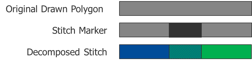
Figure 1: Stitch design construct and decomposition.
By overlapping the two colors, you can ensure a single continuous piece of interconnect, because the overlap accommodates the misalignment that can occur when each of the two colors is printed separately during manufacturing. From an odd-cycle standpoint, stitching adds another color alternation to the cycle, making it even again. Figure 2 shows how a stitch can resolve an odd-cycle error in a design.
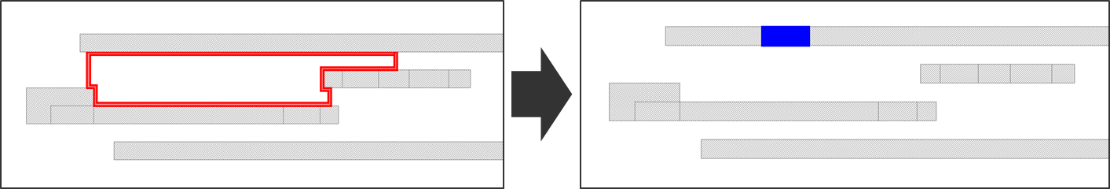
Figure 2: Stitch correction of an odd-cycle error in a place-and-route design.
Stitching is an incredibly useful technique, and can be a great way to fix a DP problem that might be difficult to fix otherwise. The fact that the process of generating these stitches can be automated is even better. Electronic design automation (EDA) DP tools can automatically fix many DP odd-cycle issues without changing the basic layout. Not all foundries support stitches, but for those that do, stitching provides a potentially very powerful error-fixing solution.
So, who wouldn’t want auto-stitching? “It automatically fixes my problems! It’s what I have always dreamed of!“ Let’s look at some DP designs using auto-stitching in their decomposition and checking flows. Figure 3 shows some metal layers on a place and route (P&R) block, and how the odd-cycle error counts compare if you run the DP process with and without auto-stitching.
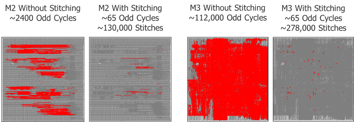
Figure 3: P&R block routing layer odd-cycle errors without and with auto-stitching.
That is a very significant difference. It is impressive how many issues can be automatically resolved this way. So again, who wouldn’t want auto-stitching? Well, for every bright side, there is a dark side. Be honest, you knew that was coming.
The first key observation in this example is that the design team never actually saw the results of the runs without auto-stitching. These runs were only performed after the fact as part of a post-mortem experiment. Because auto-stitching was the default mode of DP decomposition and checking in their flows, the team only saw the results from the runs with auto-stitching. Granted, the results aren’t completely clean, but they also aren’t so bad that they would raise too many eyebrows.
However, if someone had run DP checking without auto-stitching, and seen the results from the output of their router, the entire flow would have been stopped, and everyone would have been researching what went wrong. But because they saw the results with auto-stitching, no one gave it a second thought.
You may be thinking “Wait a minute, if there were really that many odd-cycle issues in the P&R run, then wouldn’t the built in design rule checking in the router find and flag them?” In fact, the router did flag them. But the results seemed SO bad that no one thought the router could be so wrong! They assumed that something must be wrong with the design rule checking (DRC) in the router. So they did what most people do. They ran the Calibre Multi-Patterning process on the layout to see if the results correlated. When the Calibre run came out so much better, they assumed they were right, and started ignoring the DRC results from the router!
What they didn’t understand is that the router does not perform auto-stitching, and was looking at the design as it is, without stitches. The Calibre run was configured to utilize auto-stitching, so it fixed most of the issues and only showed the remaining DP errors. The comparison was apples to oranges, but that didn’t occur to anyone. This situation not only occurred during P&R, it also impacted the cell design verification process with similar effects.
It may not seem like a particularly critical issue, since the number of remaining DP errors were so low after the auto-stitching fixes, but the bottom line is that a whole host of intrinsic problems in the design were ignored, because they were being masked by the auto-stitching. For the chip integration teams that had to deal with these designs, it was anything but trivial. The DP issues that remained were very difficult to understand, and fixing them was even more difficult, because the fundamental design mistakes made upstream could not be undone right before tapeout.
Figure 4 shows an example of poor cell design practices that were not detected until chip integration, when it was too late to fix the root cause of the problems. On the left, some odd-cycles are shown. If you look closely at the ground rails, you can see they change thickness at some point along the cell row. Most of the cells in the library were designed with a seven-track routing scheme between the power and ground rails, but one cell design team decided that their cell would work better with an eight-track routing scheme. To make their cell line up in the row, they just reduced the width of the ground track to add the extra row. While it sounds like a creative solution, this design choice sets up intrinsic odd cycles in any cell row in which the cell is placed, as the drawing on the right demonstrates.
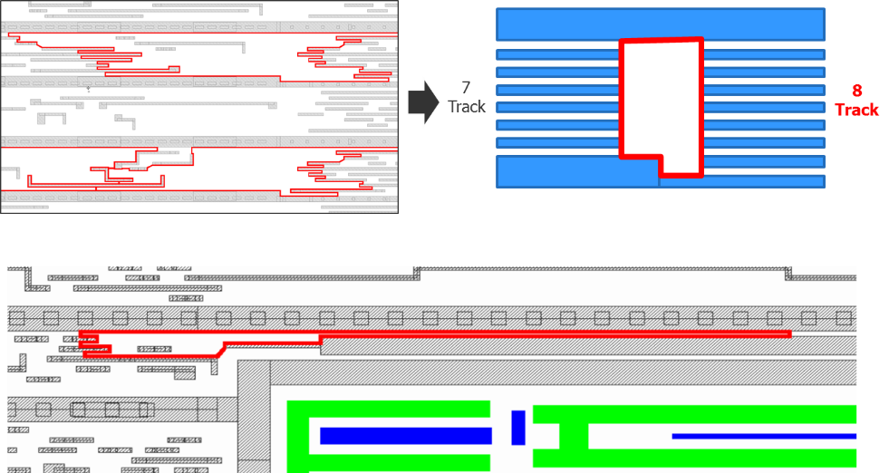
Figure 4: Cell design methodology issues causing DP odd-cycle issues.
A similar thing happened in the example shown in Figure 5. A larger piece of intellectual property (IP) was built with a ground ring surrounding it, and the IP was placed in some standard cell rows. The ground ring connects to the ground rails of the standard cells, but at the top of the cell, it extends up into the middle of the cell row, leaving a small gap between the ground ring and the power rails above it. The design team filled that gap with a one-wide line, which is part of that IP. The problem is that the line creates a color alternation cycle such that the ground and power rails in the large IP must be the same color. All the other standard cells have an intrinsic color alternation sequence that forces the power and ground rails to be opposite color. This variation creates an inherent color alternation sequence difference between the standard cell library and this special piece of IP.
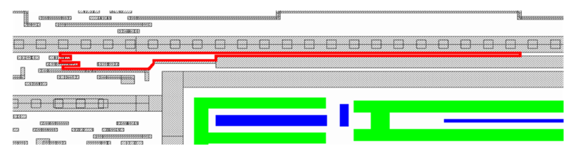
Figure 5. Cell design with IP causes color alternation error.
Why didn’t someone catch this early on, during the cell library design cycle? Certainly they did some simple placement tests, and ran DRC, didn’t they? The problem is that, in most placements of these cells, auto-stitching can overcome these intrinsic issues by inserting large numbers of stitches. In the simple placement verification tests done during cell design, auto-stitching appeared to make this design work. However, when it came to the large-scale designs, there were so many occurrences that some small percentage of them could not be fixed.
In Figure 6, a large piece of IP with eight-track rows is placed into a standard cell region with seven-track rows. Without stitching, the layout lights up like a fireworks display. However, with auto-stitching turned on, most of the issues are resolved. In the simple placement tests done during cell design, all of the issues were probably resolvable. In this large-scale block, some issues cannot be resolved. If the simple placement tests had been run without auto-stitching, the design issue would have been caught immediately, and this cell would never have been given to the block designers to use. Because that didn’t happen, the chip finishing team was forced to try to clean up the remaining issues without the benefit of redesigning the fundamental issue in the cell.
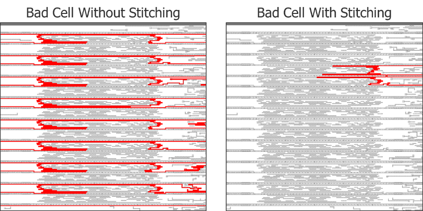
Figure 6: Odd-cycle errors in bad cell placed into block, with and without auto-stitching.
However, it wasn’t only a cell design issue. Let’s look at some of the other issues found in the router that were ignored until it was too late. Figures 7 and 8 show some odd-cycle errors at the block level that auto-stitching couldn’t resolve. Although their numbers were relatively small, the root cause behind them was actually pervasive throughout the block. However, since most of the issues were fixed by auto-stitching, no one thought about spending valuable time improving the router configuration to fix the fundamental root causes.
In Figure 7, we see two problems demonstrated. The first is wrong-way routing, and the second is off-track routing. Both of these design practices can change the color alternation sequence in a local region, compared to the majority of the layout. The result is a high probability of producing odd-cycle errors, unless the router is exceptionally intelligent, or the design team drastically constrains the use of these routings in the router configuration. Let’s just say that the native intelligence of most routers is not up to recognizing these design issues, and most design teams will not instinctively understand the implications of using these routings, because results like these mask the underlying issue. As we saw in earlier examples, the router in this case also produces hundreds of thousands of odd cycles, but most of them are masked by the hundreds of thousands of stitches that are added to try and fix them.
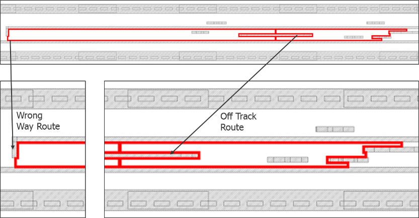
Figure 7: Example odd-cycle issues caused by wrong-way and off-track routing.
Similarly, allowing the router to do single-track jogs makes it prone to producing odd-cycle errors (Figure 8). While design teams typically constrain the router to only allow even-track jogs to avoid such issues, forgetting to do so can lead to thousands of odd-cycle occurrences that are mostly masked by the auto-stitching fixes.

Figure 8: Odd-cycle issues caused by single track jogs.
Regardless of all of these cell design and P&R issues, at least the number of errors remaining by chip finishing was relatively small, right? That is true. Auto-stitching fixed the majority of the issues. But the remaining errors turned out to be exponentially more difficult to understand and fix precisely because of auto-stitching. Let’s take a look at why that happens.
In Figure 9, the left picture is a portion of a layout run without stitching. There are two odd cycles. Each of them is reasonably easy to make sense of, as each one touches an odd number of individual polygons and resides within a single standard cell row. But, this is not what the chip finishing engineers saw. They saw the result on the right, run with auto-stitching. There is only one odd-cycle instead of two, but look closely. The odd-cycle ring passes right through a polygon from one standard cell row to the next. That is because it is passing through a stitch that was added to try to resolve this odd-cycle configuration, plus other errors not visible in the picture. The designer doesn’t see the gap in the layout from the router, because it wasn’t there. It was inserted by the Calibre Multi-Patterning functionality during the verification and decomposition run. The designer would have to look at the decomposed data to see it.
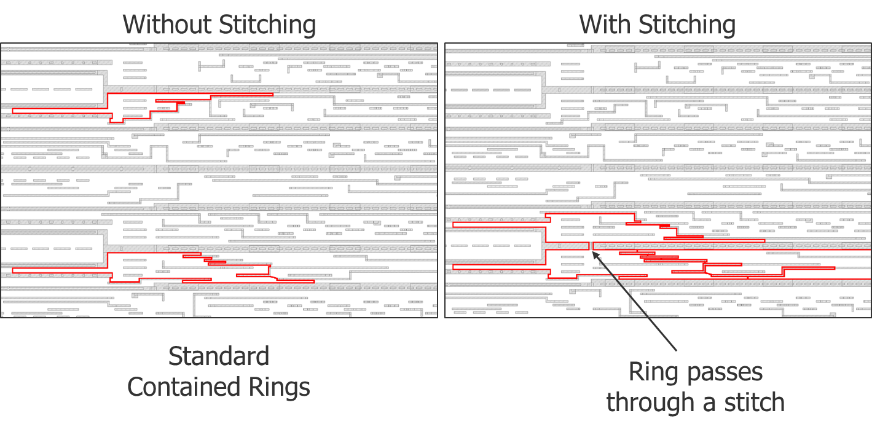
Figure 9: Complication in odd-cycle error visualization when stitches are present.
In this case, the chip finishing engineers had no idea what was going on. They didn’t know why the ring looked like this, or what they could (or should) do to fix it. They also didn’t notice that the real issue here is the two cells on the left edge that split the power rail into two parallel paths. Every time one of those cells is present, an odd-cycle error like those shown on the left occurs. But, with auto-stitching turned on, most of the odd-cycle errors were fixed, so the repetitive nature of the problem was not apparent.
The end result is that the chip finishing team spent weeks working on the remaining errors. Much of that time was spent just trying to understand what was happening. When they finally figured out the fundamental design issues that were the root cause of all of these errors, it was too late to fix the design at that level. Let’s just say that to meet their tapeout schedule, a lot of funky tricks were used to fix layout issues that would never even have occurred if the design problems had been identified and fixed upstream.
Now, don’t get me wrong. I am not saying that auto-stitching is a bad thing. Designers just need to be careful and strategic when using it. I recommend completing all of your fundamental library development and tool configuration setup and testing without auto-stitching, so you can see what is actually going on. If you see lots of systemic errors at this stage, you need to fix your methodology or tool setup to get rid of those systemic issues.
Let me be clear, though. Despite your best efforts, you will probably still have some remaining issues that you just can’t eliminate systemically. When have you ever seen a P&R tool produce a perfectly DRC-clean layout? That’s why you run sign-off DRC. You expect some level of problems to fall through the cracks. But you shouldn’t expect the P&R tool to be generating hundreds of thousands, or even millions, of DP errors everywhere in the layout. If it is, then you have some design work to do, or you need to contact your design tool vendor.
When your design library and tools are working well, and only a reasonable number of DP issues are occurring, then it is time to turn on auto-stitching. Since there are so few errors to begin with, it may be able to fix them all. If not, at least the remaining number of errors left will be very small, and much more manageable.
Think of it like this. Medicines can help cure many illnesses. But you don’t take them all the time, just in case you get sick. If you do, you might mask a more dangerous underlying problem. If you try to live your life as medicine-free as possible, it will be easier to detect when something out of the ordinary happens. Then you can take the specific medicine you need for the specific illness you need to cure.
Auto-stitching is some amazing medicine. But use it wisely, in the right amount and at the right time.
Author
David Abercrombie is the advanced physical verification methodology program manager at Mentor Graphics.

Liked this article? Then try this –
White Paper: Assume Nothing: Clearing Up Common Misconceptions About Multi-Patterning
This article was originally published on www.semiengineering.com