How Do I ECO a Multi-Patterned Design?
By David Abercrombie and Alex Pearson, Mentor Graphics
Applying ECOs to multipatterned designs can be a nightmare, unless you plan ahead

A lot has been written and discussed about how to decompose (color) layouts for advanced process nodes that require multipatterning (MP). However, one topic that has been sorely ignored is how to efficiently make changes to designs that are already colored, or even taped out and processed. We tend to act like all designs work out the first time through, but in reality, this is unfortunately not the case.
Sometimes an issue with a design may be found very late in the design process, requiring changes to the layout. Sometimes there are yield or performance issues with designs manufactured in silicon and a design change is needed to fix the cause of those issues. Such design changes are typically called engineering change orders (ECOs). Many times, the changes are quite small, but nonetheless, they are changes in the layout. In MP designs, even small changes can wreak havoc on coloring (and consequently, time to market) if not dealt with appropriately. We need to proactively develop tools and flows to provide a complete ECO enablement solution, before these issues consume resources and destroy schedules.
At first glance, you may ask yourself what the big deal is. If the design needs to be changed, can’t you just rip all the colors out, make the edits, and then recolor the whole design again? It turns out that this is similar to fixing a scratch on a car by taking all the body panels off, dipping them in an acid bath to strip the paint, repainting them, and putting them back on the car again. It works, but it costs a lot of time and money, and your car might be an entirely different color when you’re done.
Assuming you used a good hierarchical “color as you go” design flow in which you colored each piece of intellectual property (IP) as you built up the chip, and performed your timing analysis at each step to make sure everything worked well, you probably ended up with a very hierarchical set of colored data, and nicely-tuned performance. If you rip all that out and recolor the entire design at the full-chip level, you could not only destroy the hierarchy of the colored data, but also change the coloring of a significant percentage of the design, such that you would need to redo detailed timing analysis for everything.
Let’s walk through a simple example. In your original flow, you may have colored an IP block and performed timing analysis, then placed that colored block multiple times into the top-level chip. Not only do you know what the timing is of that block, but since it is colored at the block level, all placements of that block have the same coloring. If you rip all that color out and now try to recolor at the top-level, you could not only get different colors than you did the first time, but each placement may have different colors compared to the others. Now not only do you have to redo all your timing, but that timing can vary between instances of the block because of the varying colors.
The key to recoloring an MP layout during an ECO is the same as making any design modification during an ECO—you want to change as little as possible. The less that changes, the less likely that you introduce other unwanted effects in the rest of the design, the less recharacterization you have to do, and not to mention, the less work you have to do in making the changes themselves. The question becomes, how do you limit what you have to recolor during an ECO, and how do you make those coloring changes while leaving the rest of the design coloring intact? Perhaps an even better question may be, can you get software automation to do it all for you?
Well, yes, there are automated solutions. While we’re not familiar with all of them, the Calibre Multi-Patterning functionality provides an automated approach that applies a “smart ECO re-coloring” flow to automatically minimize changes to coloring during an ECO design change. Using this flow as our example, here are the key steps, as shown in Figure 1.
- Identify the polygons that changed during the ECO by comparing the original design to the modified one.
- Based on the modified polygons and opposite color spacing requirements, determine the extended set of polygons (i.e., connected components) whose color must be re processed to avoid same-mask color violations.
- Determine a new legal coloring for this subset of the design, or flag noncolorable issues caused by the design modifications.
- Assuming a legal coloring exists, combine the newly-colored portion of the design with the original colored data from the rest of the design into a new fully-colored modified design.
- Run the DRC signoff deck on the final redesign.
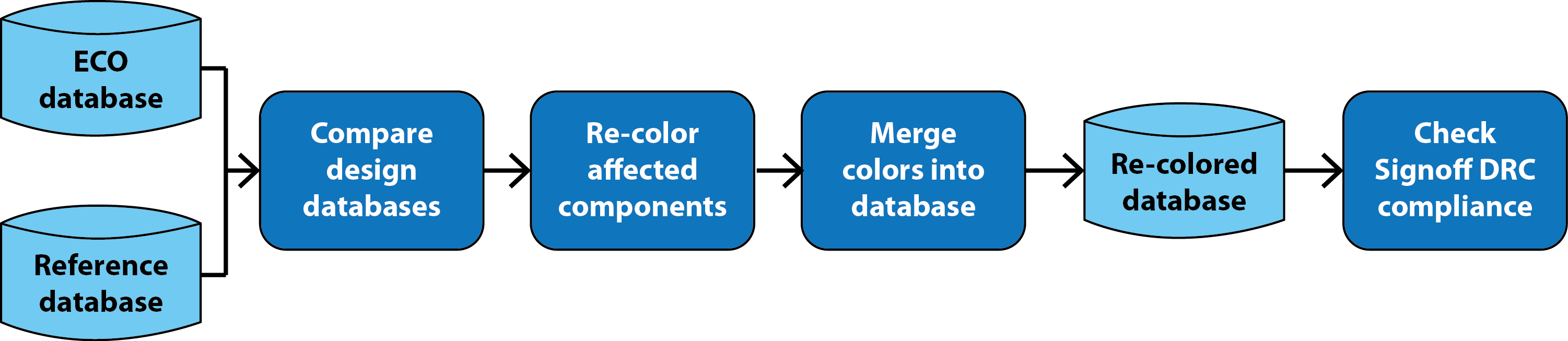
Figure 1: Smart ECO re-coloring flow.
Let’s see how this works in an actual double-patterned (DP) layout. Figure 2 shows a portion of two routing layers in a typical layout. The left image shows what this portion of the layout looked like before coloring, while the right image shows the original colors that were generated.
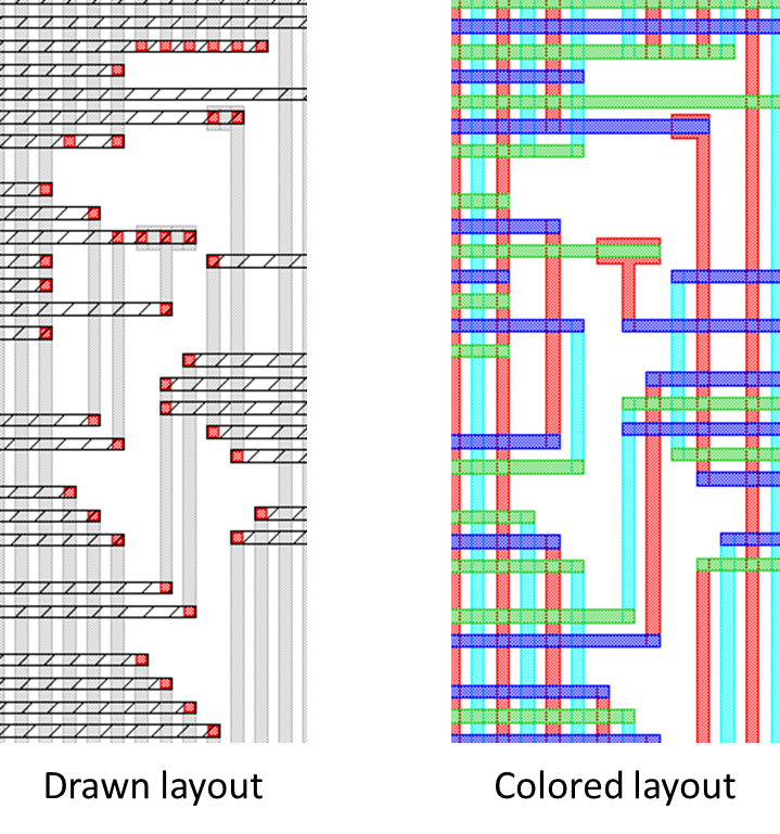
Figure 2: Original drawn and colored layout of two metal routing layers.
For some reason, this design does not work as expected, and the design team determines that it can be fixed via an ECO by rerouting a small portion of the layout. Figure 3 compares the original uncolored layout with the same area after the ECO routing changes.
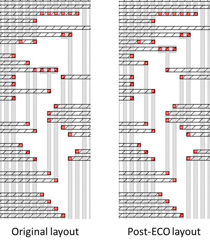
Figure 3: Original uncolored layout compared to the ECO modified layout.
Now you can compare the two layouts and identify exactly what was modified. Figure 4 highlights the polygons that were changed during the ECO.
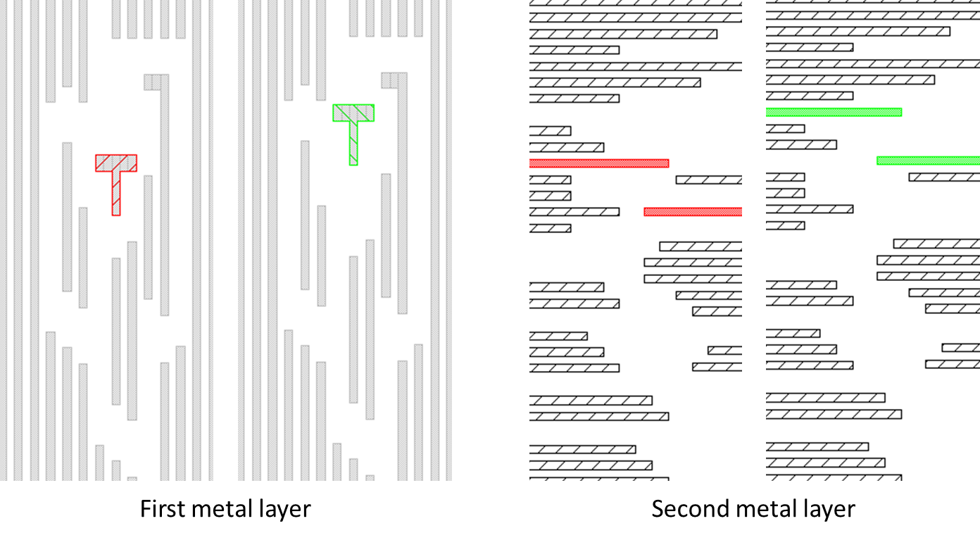
Figure 4: Polygons changed during the ECO reroute.
Next, it measures the spaces between the polygons on the new layout to determine which sets of polygons form connected components that require color alternation. Figure 5 compares the connected components in the original design to those in the ECO changed design. The modified polygons are highlighted, along with the extended set of polygons that need to be recolored due to their being part of a group of connected components containing at least one modified polygon.
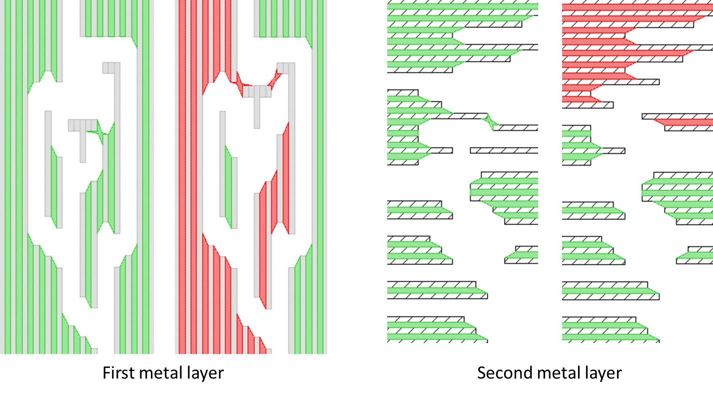
Figure 5: Comparison of connected components before and after the ECO changes (red components need to be re-colored).
The tool then performs coloring on just the small portion of the layout impacted by the ECO changes. This limits the changes, and significantly improves the runtime compared to rerunning the entire design. Figure 6 shows the new colors that were generated.
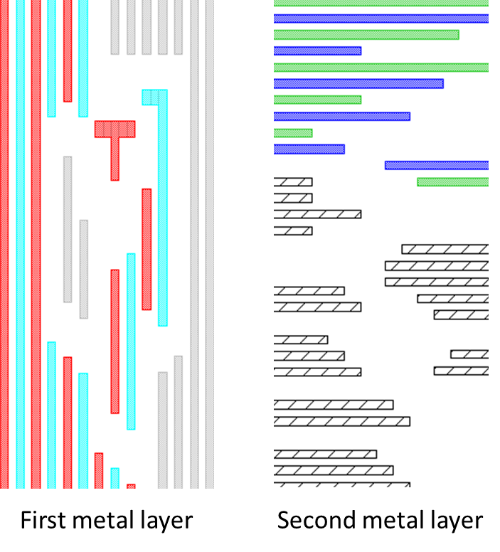
Figure 6: Re-colored components required by the ECO changes.
Now the automated process can pull the colors from the original design that did not have to change, and merge them with the newly-colored data to form a completely colored database. Figure 7 shows the data pulled from each database, and the resulting combined set of colors.
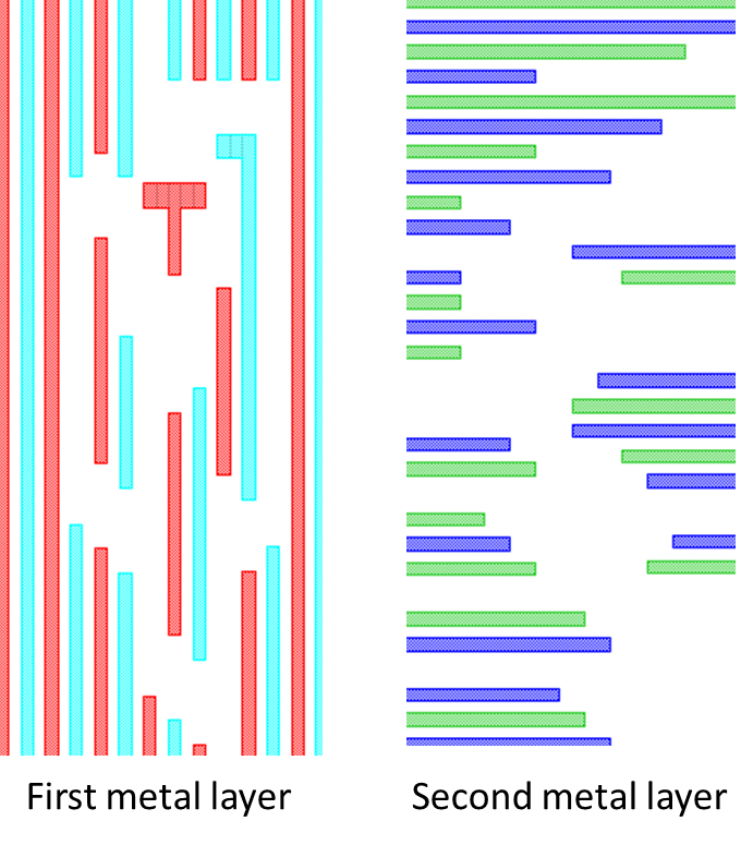
Figure 7: Original colors from the unchanged portion of the layout merged with the new colors from the changed portions in a single, completely-colored layout.
This layout is now ready for a final signoff design rule checking (DRC) run to verify everything is good to go. Figure 8 compares the final re-colored ECO layout with the originally colored design.
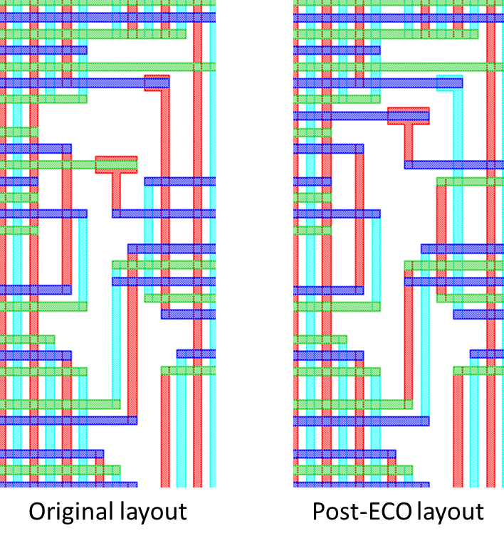
Figure 8: Original colored layout compared to the newly-colored ECO changed layout.
This automated ECO solution has many advantages over alternative approaches.
- First, the entire flow can be automated into a single script that performs all the needed operations outlined in the flow.
- Second, this approach limits re-coloring to the smallest set of polygons required by the actual ECO design changes, which in turn limits the impact on timing and runtime, as well as any loss of data hierarchy, that results from making the coloring changes. If you try to accomplish these same results by manually determining the minimum set of polygons that need to be re-colored, you will quickly find that it is a very difficult and error-prone activity.
- Finally, the particulars of this scripted flow could easily be adapted to fit the unique differences of any design teams’ particular use model or database integration methodologies.
The need for ECO design changes is a fact of life in integrated circuit (IC) design. Colored, multipatterned design layers introduce new complications to this process. The “smart ECO re-coloring” flow we’ve described here provides an efficient, automated solution for applying ECOs to layouts while minimizing the potential negative impacts caused by alternative methods.
If you’re struggling with applying ECO design changes in multipatterned design processes, this flow may give you some insight into a better solution. Until then, here’s hoping that all your designs come out perfectly the first time!
Authors
David Abercrombie is the advanced physical verification methodology program manager at Mentor Graphics. For the last few years, he has been driving development of EDA tools that can solve the issues in design to process interactions (DFM) that create ever-increasing yield problems.
Alex Pearson is a Calibre Technical Marketing Engineer in the Design to Silicon division of Mentor Graphics, currently focused on multipatterning techniques for physical verification at advanced process nodes.

This article was originally published on www.semiengineering.com


