New RTL Modeling Constructs in Verilog
I’ve been packing up my office as Siemens is closing my location. This marks the longest I’ve ever spent in a single office, a whopping 15 years. Coincidentally, I was in the same building earlier with another company, Avant! for an additional 2 years. I’ve got a box of stuff from previous jobs that I rarely unpack. But it happened to go through it and found the proceedings from what was to become the first DVCon in 1992. I doubt these proceedings exist anywhere in digital form.
In the proceedings was a paper I published about a new RTL modeling construct I added to Verilog before it became an IEEE standard. It eventually became known as a NonBlocking Assignment (NBA). Before discarding it, I thought I’d scan it and share it here. After dealing with wires and registers, this is the probably second most challenging topic for people learning Verilog. Note that this paper was published a year before any other tool besides Verilog-XL had implemented the language. The terms Verilog-XL simulator and the Verilog language were interchangeable. This is also before the IEEE 1364-1995 LRM adopted the terms “active region” and “NBA region” for the event queues.
As the Program Chair of the 35th DVCon, I invite you to read my paper from the inaugural DVCon. I would also be delighted to have you join me at DVCon in person from March 2 to 5, 2026 at the Santa Clara Hyatt Regency.
New RTL Modeling Constructs in Verilog
Abstract
New RTL modeling constructs have been added to the Verilog Hardware Description Language. Before these constructs existed, designers had difficulties modeling true RTL-level descriptions.
This paper presents several applications of the new Verilog RTL modeling constructs. Higher-level modeling applications such as pipelines using the new constructs are presented.
Introduction
The Verilog Hardware Description Language (HDL) has recently been enhanced by the addition of new Register Transfer Logic (RTL) modeling constructs. These enhancements represent a significant improvement in the ability to write higher-level RTL models in Verilog.
The new RTL constructs eliminate the ambiguities—found in previous versions of the Verilog HDL— that occur in register assignments when writing to and reading from a register at the same clock edge. The new constructs provide ways to describe RTL assignments that span multiple clock cycles.
Classic RTL simulation
There is no one particular definition of an RTL modeling style. Primarily, RTL models describe the synchronous transformation of data from one set of registers to another. Time is defined in a granularity no finer than a clock cycle. The only circumstance where one needs the absolute value of time is in the definition of external clocks.
A classic RTL description lists the register assignments that need to occur on each clock edge as shown in Figure-1. Each line represents a synchronous transfer of data to the registers on the left-hand side of the “<—” operator.
Figure-1
  TO: IR<-MEM[PC]; PC<-PC + 1;
  T1: AC<-IR; IR<-MEM[PC] ;
  T2: IF (X) GOTO T6;
  T3: PC<—PC + 2;
The flow diagram in Figure-2 shows two distinct processes for evaluating expressions and updating registers. The inner loop represents fanout settling within the current simulation time. A true unit delay simulator would not have the inner loop and must advance time before reevaluating any registers. This is not a problem when modeling pure sequential logic.
The outer loop represents the advancement of simulation time. This is typically the next clock edge or state transition in the described system.
Figure-2 RTL simulation flow
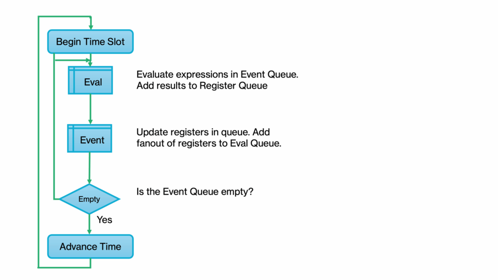
However, most designs contain some combinational logic, which cannot be easily modeled at the behavioral level. Until delay simulators are not always the desirable choice when simulating these mixed gate and behavioral level models. Event-driven simulators can simulate mixed-level models with realistic delays more efficiently than unit delay simulators.
Event driven simulation
Verilog-XL™, like most event-driven simulators, uses a zero-delay event queue. An event can be a change on the output of a gate or the execution of a procedural statement. Events execute one at a time, creating new events that get placed at the end of the queue. When the queue empties, the simulator advances time to the next scheduled event.
Figure-3 shows a flow diagram for an event-driven simulator. The major difference between this diagram and Figure-2 is that the evaluation and register update processes have been combined into a single event-processing algorithm. Verilog-XL combines the inner loop with its event-processing algorithm, producing a very efficient simulator.
Figure-3 Event simulation flow
Register assignment statements are common events in an RTL model. The value of the registers receiving assignments changes as each statement executes, destroying the previous contents.
One characteristic of event-driven simulators is that they do not always guarantee the order in which events execute. Subsequent statements must use the new value of the register since the old value is lost. It is not possible to predict whether a statement will be using the old or new value of a register without enforcing some kind of explicit ordering.
Race conditions in simulation
The Verilog assignments in Figure-4 are an example of what can happen when executing muldple blocks of register assignments on the same clock edge. In this example, there are three concurrent blocks, each assigning a different register. The registers A and B are supposed to exchange values the next clock cycle when the register SWAP is true.
Figure-4
  input input1, input2, clock;
  reg A, B, SWAP;

  always @(posedge clock)
    if (SWAP)
      begin : block1
        A = B;
      end
  always @(posedge clock)
    if (SWAP)
      begin : block2
        B = A;
      end
  always @(posedge clock)
    if (input1)
      SWAP = 1;
    else
      SWAP = input2;
A Verilog-XL simulation of the example in Figure-4 yields unpredictable results in the contents of registers A and B. There is no way to know which of the three blocks of assignments would take place first when the clock edge event occurs.
If the statements execute in the order they appear, the first two blocks would use the old value of SWAP from the previous clock cycle. Register A gets the old value of B, but B gets the new value of A, which leaves A unchanged. A different ordering leaves the value of B unchanged and the value of A set to the value of B.
It is possible to remove the ambiguities in the previous example by inserting delays and adding additional signals. Figure-5 shows the previous example re-written with a combination of techniques to remove ambiguities.
Figure-5
  input input1, input2, clock;
  reg newA, newB, SWAP;
  wire #1 A = newA,
          B = newB;
  always @(posedge clock)
      if (SWAP)
          begin : block1
              newA = B;
          end
  always @(posedge clock)
      if (SWAP)
          begin : block2
              newB = A;
          end
  always @(posedge clock)
      if (input1)
          SWAP = #1 1;
      else
          SWAP = #1 input2;
Now the registers A and B swap as intended because of the temporary wires created. Also, the old value of SWAP is used in the if statements because of its delayed assignment.
There are several problems associated with these workarounds. The foremost is the added complexity of writing the model, adding extra statements just to get the simulation to work. At the same time, the extra statements reduce the performance of the simulation. Synthesis tools can get confused and create superfluous logic, typically extra storage devices.
New assignment operator
A new RTL assignment operator addresses these problems by creating a mechanism to clearly define the event ordering in behavioral models. The RTL assignment operator puts register assignments into a separate event queue that executes after the zero delay event queue. Because this operator is non-blocking, succeeding statements execute without waiting for the previous assignment to complete.
The syntax for the RTL assignment statement is described in Figure-6.
Figure-6 Syntax
<registers> <= [<event>] <rhs_expression>
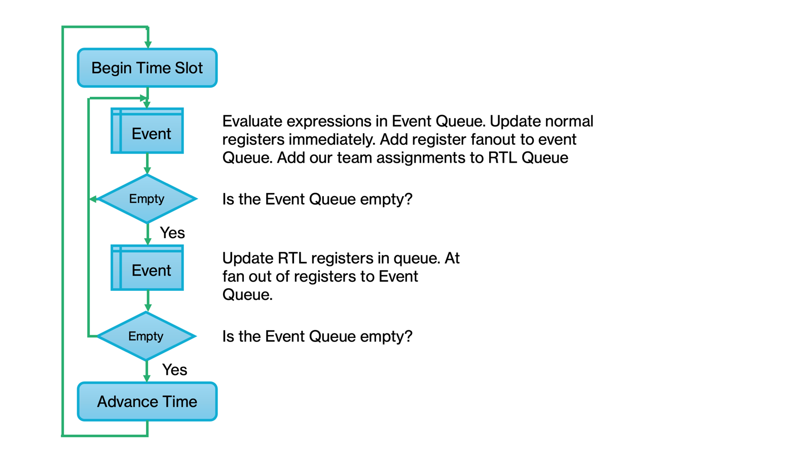
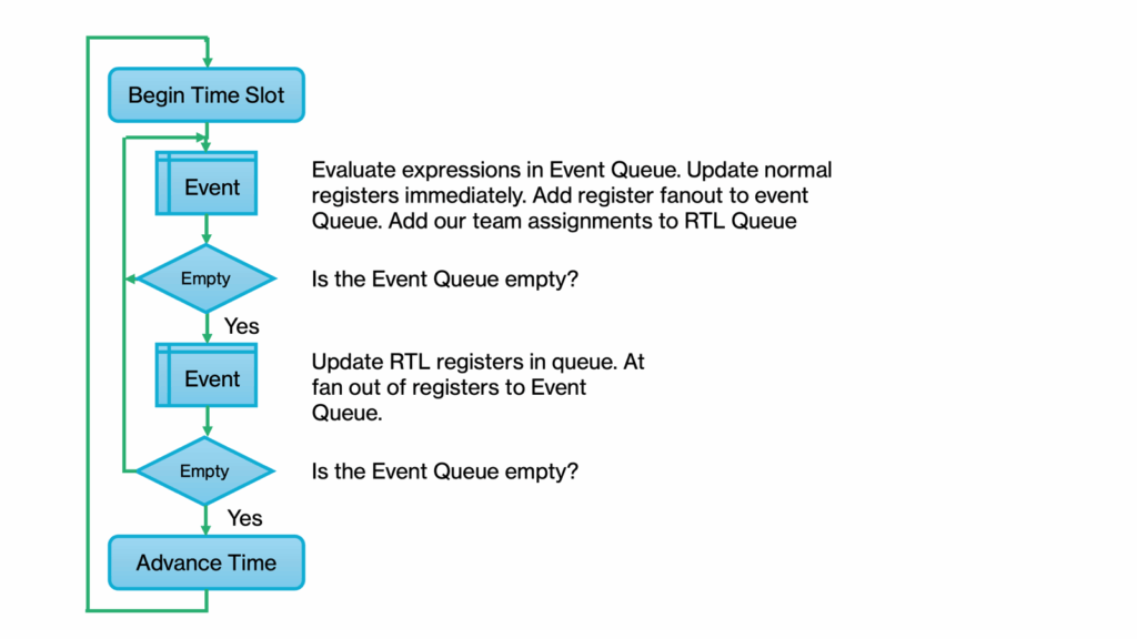
The <rhs_expression> evaluates immediately along with any indices used in the <registers> when the statement executes. Their values are placed in an RTL queue, shown in Figure-7. The registers in the <rhs_expression> update after the zero delay event queue finishes.
Any events created by the updated register are placed onto ihe next zero delay event queue.
Figure-7 Enhanced RTL event flow diagram
Some examples of statements using the new RTL assignment operator are shown in Figure-8.
Figure-8
  // Simple RTL assignment
  A <= B;

  // Register Swap
  {A,B} <= {B,A};

  // Delayed assignment
  A <= #5 B + C;

  // Event controlled assignment
  A <= @(posedge clk) B;

  // Memory Update
  MEM[addr] <= @(P2) data;
The last example in Figure-8 demonstrates a solution for another problem with procedural assignments. The index value addr is read at the same time as data, not when making the actual assignment to MEM.
Figure-9 shows the example in Figure-4 rewritten by replacing the procedural assignment operator with the new RTL assignment operator.
Figure-9
  input input1, input2, clock;
  reg A, B, SWAP;
  always @(posedge clock)
        if (SWAP) begin
                    A <= B;
                  end
  always @(posedge clock)
        if (SWAP) begin
                    B <= A;
                  end
  always @(posedge clock)
        if (input1)
             SWAP <= 1;
        else
             SWAP <= input2;
Regardless of the order in which these blocks execute, registers A and B swap correctly, and the first two blocks use the old value of SWAP. Verilog-XL executes all three blocks within the same zero delay event queue, then updates all of the registers in the RTL assignment queue.
Transport delay
Because the RTL operator queues assignments to registers, multiple assignments to the same register can be scheduled at the same time. This characteristic makes it possible to model transport delays, which describe the behavior of devices whose outputs change faster than the inherent delay through the device.
Without this new construct, the simulator may produce incorrect results. In the example in Figure-10, the RTL assignment operator (to Out3) is compared with the blocking assignment operator (to Out1) and a continuous assignment (to Out2) in a combinational logic description.
Figure-10 Transport delay
  always @(A or B)
            Outl = #100 A & B;

  assign #100 Out2 = A & B;

  always @(A or B)
            Out3 <= #100 A & B;
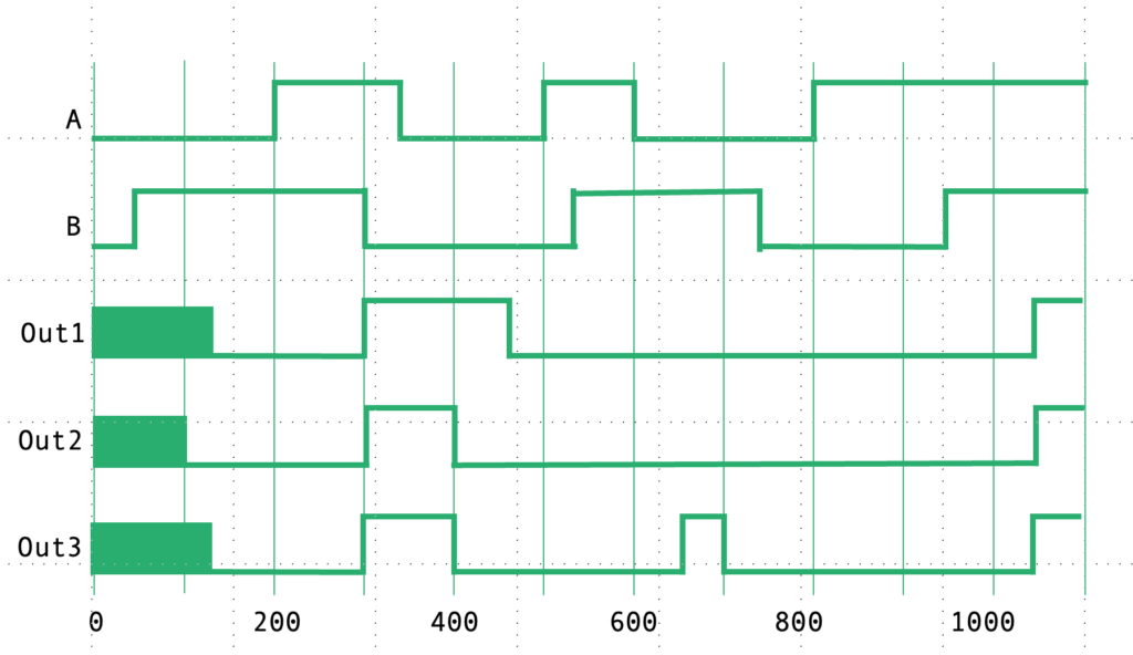
The initial pulse at time 300 on Out1 is longer than the pulse on Out3 because the simulator misses the change on signal B. It is not until time 350 that the simulator observes a change on signal A and sets Out1 to 0. Outl is missing the second pulse at time 650 because the simulator misses the change on signal B at time 550. Out2 has the correct first pulse but misses the second pulse.
Multi-phase clocks
An event control may be used to postpone an RTL assignment until after the event occurs. The event control may be a delay or a change on a signal. This feature enhances the modeling of designs using multi-phase clocks. The expression evaluates on one clock edge and is assigned on another clock edge. In Figure-11, the register membus now functions properly as a master-slave flip-flop.
Figure-11 Two-phase assignment
  reg [31:0] membus;
  reg WR;
  always @(negedge PHI)
       if (write enable) begin
            membus <= @(posedge PH2) data;
            WR <= 1;
          end
       else
          WR <= 0;
RTL-level pipeline descriptions
The non-blocking feature of the RTL assignment is useful when describing pipelines. Ordering the assignments in each stage of the pipeline so that it simulates correcdy is unnecessary.
Figure-12 is an example of a 16-bit pipelined shift and add multiplier. Keep in mind that the assigned register’s index is evaluated when the statement executes, not when making the assignment.
Figure-12 Pipeline Multiplier
  always begin : mult // P=X * Y(t)
    integer i;
    @ (ph1)
    for (i=0; i < 15; i=i+l) begin
      Y[0} = Yt;
      Y[i+1] = Y[i]*2;
      if (X[i])
        product [i+1]<=@.(ph2) product[i]+Y[i];
      else
        product[i+1]<= @(ph2) product[i];
    end
  end
  assign P = product[15];
High-level pipeline descriptions
Another recent enhancement to the Verilog Hardware Description Language is the ability to put a repeat count on an event control. This is useful when describing operations that require multiple clock cycles to complete.
This feature, combined with the transport delay functionality of the RTL assignment operator, provides a method of modeling pipelines at a higher level that was not formerly possible. The multiplier in Figure-12 can now be written in a single statement, as shown in Figure-13.
Figure-13 High level multiplier
  always @(negedge phi)
     P <= repeat (15) @(posedge ph2) X * Yt;
Summary
These enhancements to the Verilog Language let engineers clearly define RTL models without the need for unnecessary complexity. Engineers will be able to improve the performance of their simulations because of this reduced complexity.
Furthermore, these enhancements provide higher-level modeling capabilities for pipeline and multi-phase designs. This enables engineers to focus on their design instead of the design of the simulator.
Bibliography
- 1. van Cleemput, W.M., “Computer HaTdware Description Languages and Their Applications,” Proc. l6th Design Automation Conf., June 1979,pp.554560.
- 2. Miczo, A., “Digital Logic Testing and Simulation,’ Harper & Row, New York, 1986,pp.357-361.
- 3. Cadence Design Systems, “Verilog Reference Manual,” 1991.
- 4. Cadence Design System, “Modeling Style Guide for Mixed-Level Synthesis,” 1991.


Comments
Leave a Reply
You must be logged in to post a comment.
Dave, this post is a wonderful reflection on the evolution of Verilog and SystemVerilog.
It’s impossible to read it without thinking about the incredible impact you’ve had on it and this industry. From the early days of what became DVCon to your technical leadership roles across many EDA companies, you’ve been the engineer’s engineer: deeply technical, visionary, and always generous in sharing knowledge. The respect you’ve earned globally from students, design and verification engineers, and all in the EDA industry speaks volumes about your contributions.
It’s been a privilege to have you guiding the language and methodology that shaped modern verification, and I can’t wait to see what you have in store for us at DVCon U.S. 2026. I will certainly see you there!
P.S. We should probably work to scan the 1992 proceedings and add them to the Accellera DVCon proceedings archive site.