How fast can you simulate a 45 MVA Power Transformer from production CAD import?
Does this sound familiar – the next project meeting is due in a week or so, and you promised some preliminary results, but the defeatured CAD import from the design team hasn’t landed in your email. You ping them but now you can only wait. They offer you access to the whole design CAD assembly.
Do you wait on them, or do you play around with the design CAD?
Just like most EMAG engineers, you have reservations about your CAD prowess, but you must meet the deadline. The question is, how fast can you set up your EMAG model, without over-refinement by defaulting to the feature-rich geometry of the design CAD? You check in with the CAD gurus and they send links with how-to videos on basic geometric modeling. Armed with these and their willingness to answer basic questions, you start your EMAG journey in a CAD-centric environment.
Why you can’t use the design CAD
Design CAD communicates a detailed description of the final product, distributes the real estate among the components of a system, and is of just enough tolerance to manufacture the part. It lacks some of the innards needed to complete an EMAG analysis, and with the inclusion of bolts, threads, chamfers, blends, branding, etc. it is too detailed.
As EMAG users, we prefer to use the in-built CAD modelers of the general-purpose EMAG solutions (like Simcenter MAGNET, and dedicated ones like Simcenter SPEED or Simcenter Motorsolve for electric motors). These are fit for purpose and are bulletproof in terms of meshing. That is, you are sure the meshing will be successful. In a collaborative environment, the design CAD needs to effectively adapt to significant vertical changes, including material switches based on cost and availability, as well as power-density requirements such as mass and volume, and horizontal changes driven by multi-physics. The EMAG solutions should update automatically, through associativity, to reflect the geometric inputs during the development cycle iterations of the design CAD.
Failure to synchronize is costly in the long run as more time is spent fetching the latest geometry from the design CAD team, rather than in simulating and analyzing the model.
Updates and changes multiply the workload
Today, we use CAD imports for each of the physics environments. This is OK if it is a one-off affair but dealing with imports in an iterative process is non-trivial. Cleaning up the geometry (defeaturing, intersections, unconnected edges, non-manifold geometry…) can take days to weeks. Plus, different physics use different geometries and meshes. For example, air gap and rotor-geometry accuracy is important for electric motor EMAG analysis, while the flow volume surfaces accuracy is paramount for the cooling channels in a CFD thermal analysis. Substantial effort is expended when communicating these requirements to the design team, who may need to make multiple models for the multi-discipline development process.
At a minimum, the process should associate and track geometric cleaning operations – a default in a CAD-centric environment. For other CAE solutions, every time the design CAD iterates, the effort is expended once more. In other words, you may set up the process the first time only to discover that it is not robust enough to accommodate design CAD changes. Many companies use scripts to try and help standardize the process, but these scripts need to be maintained, taking up valuable human resources.
How do you extract a 45 MVA power transformer EMAG model from a detailed CAD import?
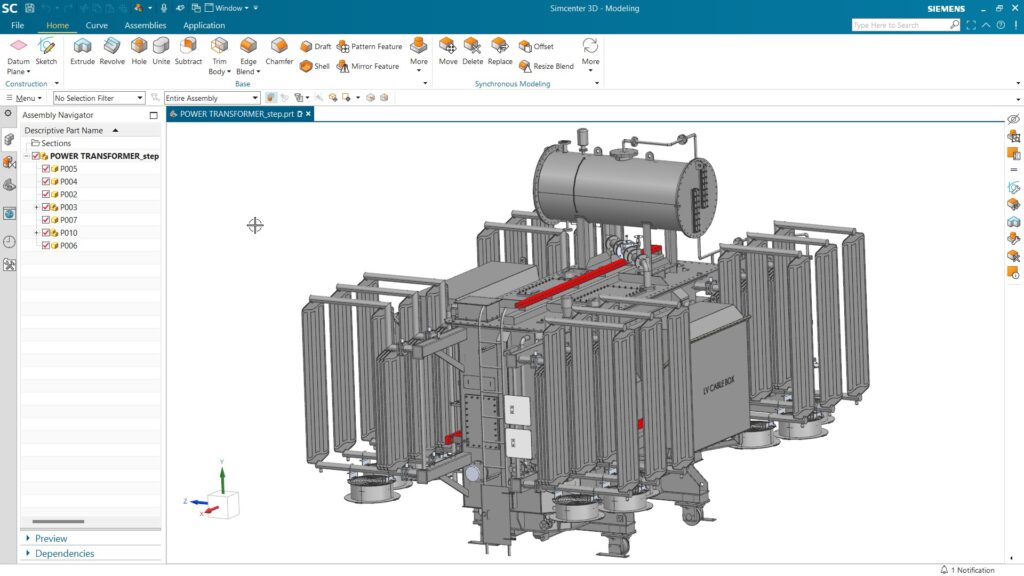
Figure 1 shows an import of this kind of transformer in Simcenter 3D with radiators, fans, tank, connection box, conservator, feet, ladder, etc. I put Simcenter 3D to task from the perspective of an EMAG user with limited CAD expertise using the following steps:
- Hide the non-EMAG assemblies like radiators and fans. A better approach if one is familiar with assemblies is to load the relevant bodies and exclude bolts, nuts, and other smaller components from the EMAG bodies.
- Then hide the detailed features of the EMAG bodies like bosses, bolts, and nuts e.g., from the transformer and tank assembles.
- Associatively copy (Wave/Promote) these EMAG bodies from the CAD design to EMAG geometry.
- Next, delete the holes, blends, and chamfers from the EMAG bodies.
- This is followed by extracting associative geometry (curves) of the windings and tank as it is easier to recreate them than defeature them. The core is simply defeatured by removing the through holes for clamping.
- Finally, the oil and air regions (airbox) are added, and the model is meshed.
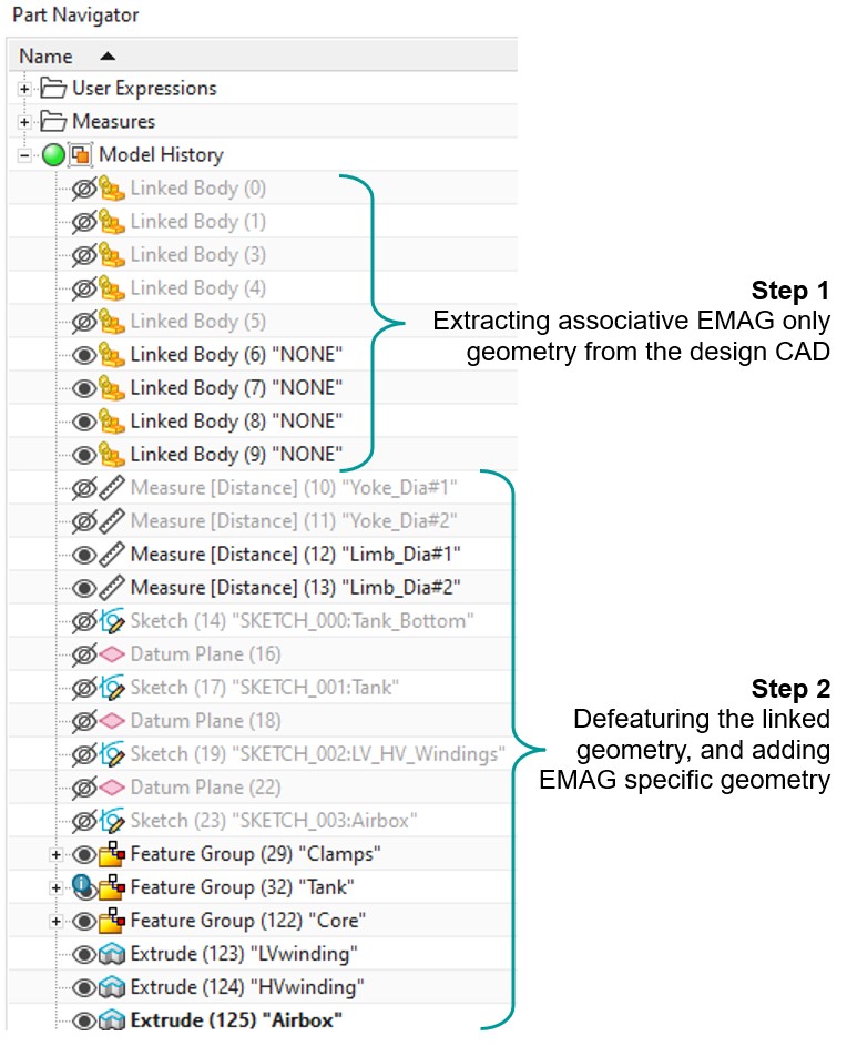
Figure 2 animates the process, which can be broken down into steps as seen in the model history. That is, extracting an associative EMAG geometry from the design CAD in the first step, and then defeaturing and adding EMAG-specific geometry like the explicit turns and airbox in the second step.
Up to this point, the difference with a standard CAE solution that supports CAD imports is associativity. Associativity is what allows you to go fast by automatically propagating the design CAD changes. In addition, these EMAG-specific defeaturing operations and additional geometries should not propagate to the design CAD as it is shared with other groups using meshes required for simulation with different physics.
The advantages of Simcenter 3D
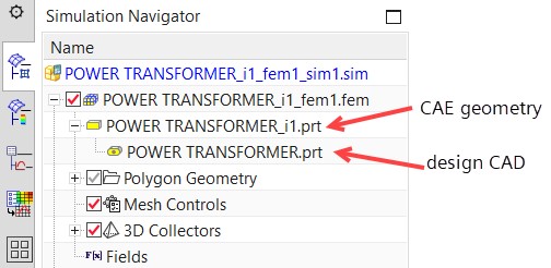
Simcenter 3D achieves this via its file system for design CAD, CAE geometry, mesh, sim and post-processing, i.e., part, i-part, fem, and sim and post respectively. This file arrangement is seen in Figure 3, without the post-processing files. That is, the user associates (Wave/Promote) the EMAG geometry in the i-part to the design CAD in the part file, and generates the mesh based on the i-part from which the sim is based. Finally, the file post is based on the sim file. Each file can be launched independently. For example, after generating the EMAG geometry there is no further need to load the design CAD part file.
Full automation with user-defined expressions
To fully automate the generation of the EMAG geometry within the space constraints set by the design CAD, you use user-defined expressions to define the design sizing rules. For transformers, this is like transformer sizing calculators. In this case, user-defined expressions (user parameters) were used to generate the explicit turns for each winding in a 2D axisymmetric model for winding loss analysis. The same geometry is usually used for high-voltage insulation strength assessment under voltage stress.
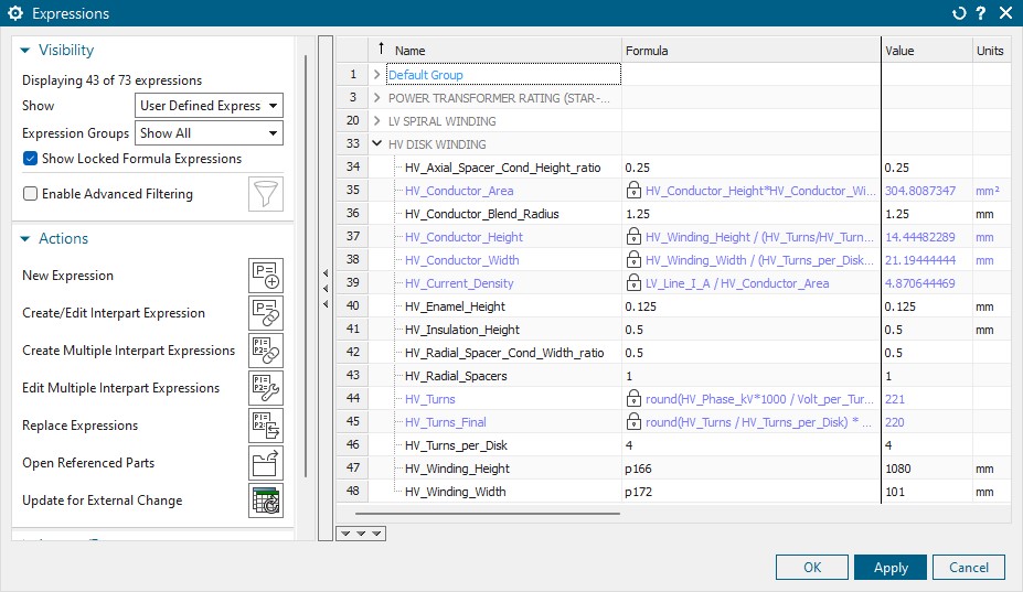
The turns including the insulation and spacers are constrained within the exterior edges of the winding by reference to the design CAD, while the number of turns, height, and width, are based on design rules.
Our current model status
At this juncture, we have all the models necessary for loss (efficiency) analysis, as seen in Figure 6. For no-load core (iron) losses, you need to model the core accurately (a stacking factor that includes the cooling ducts and laminating some core packs, considering joint effects and anisotropy, etc.), while the windings are treated as bulk. The same model is used in the stray loss analysis by adding the conductive and permeable structural bodies (tank, core tie plates, shields, clamps etc), while the core is treated as isotropic and the windings as bulk. Surface impedance boundary condition (SIBC) is applied to these structures to significantly reduce the solving time. The 2D axisymmetric model saves time in analyzing winding losses by accounting for AC frequency effects (proximity and eddy-current). The core is modified to maintain the same cross-sectional area as the 3D model.
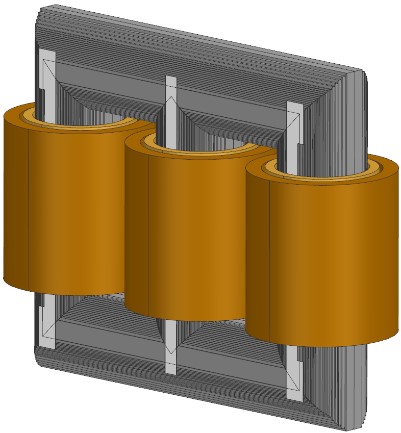
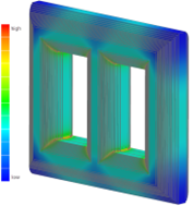
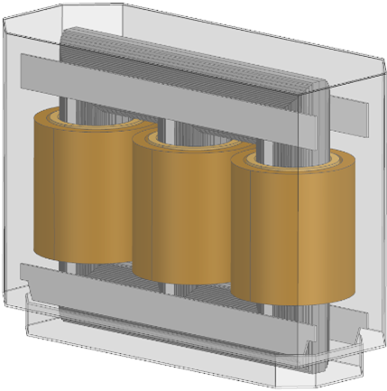
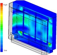
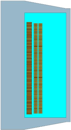
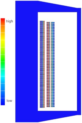
Figure 6: The distribution of no-load care (iron), stray and winding losses.
Conclusion
In summary, Simcenter 3D enables you to overcome CAD bottlenecks in prepping an associative EMAG geometry. When combined with design rules through user-defined parameters, it is possible to automate a power transformer loss analysis workflow, that is responsive to design CAD changes.
Simcenter Mechanical 2306
This blog was release as part of the Simcenter 2306 release series. More info on this release can be found here


Comments
Comments are closed.
This is a great example of how Simcenter 3D can be used to improve the efficiency and accuracy of power transformer loss analysis. As a Splunk Certification holder , I really appreciate your dedication and efforts to make this more informative.
Thanks for sharing