Power electronics in aerospace: megawatts need mega attention
The next generation of aircraft will be greener and more sustainable than ever. The first electric, hydrogen-powered and hybrid planes are planned to go into service in 2035. Not every technology is yet so mature that they will be nearly 100% emission-free or applicable to all ranges. Therefore, different technologies are considered from batteries, fuel cells, ammonia, hydrogen combustion and sustainable aviation fuel (SAF), which has been used for some time but mostly as a mixture with regular kerosene. There is still quite a way to go until we reach the carbon-neutral targets set for the industry, but we are on the good track. Such a major shift will take time for the industry and suppliers to adjust. Depending on which technology, the supply chain must be established and expanded to meet the future demands from source to end use with generation, storage and transport in between.
But what’s the difference?
Besides the different types, storage technology and their inherent properties, the biggest difference lies in their state or the state into which the fuel is converted. While SAF, ammonia and hydrogen can be burned in regular jet engines (ammonia and hydrogen need new combustion chamber designs), they can also be used to drive a generator to create electricity. Hydrogen, and potentially ammonia, can be used in fuel cells to produce electricity and, of course, there are batteries. There is also direct combustion to generate thrust, as jet engines have done for decades, and electricity, which is relatively new to the aerospace industry, at least for larger aircraft propulsion.
The big change for the aerospace industry is the major technology differences that require a complete rethinking of the whole propulsion system from fuel/energy storage to the end consumer (e-motor or jet engine). The whole integration into the airplane will also have to change, with all its unknowns and challenges for the development team and the new challenges for the certification of such new airplanes.
But what’s so complicated with e-motors and electric planes?
You’re right: e-motors have been around for a long time. In escalators, elevators, other electric machines, and electric cars for around a decade. Airplanes face pretty much the same challenges as electric cars, with the difference that the issue of a car stopping in the middle of a trip is minor compared to an airplane. The aerospace industry will face increased scrutiny and safety concerns regarding such new technologies and will apply redundant systems. Since the scandal of phone batteries burning, precautions must be taken, especially in the aviation industry.
But let’s look a bit closer at the technologies and their requirements in the aerospace industry. Whether the energy source is a fuel cell or a battery, the provided power is in the form of direct current (DC) and the motors need alternating current (AC) to run. To change DC into AC, a set of inverters is needed, at least one for each motor if no redundancy is required, as it usually is for critical systems.
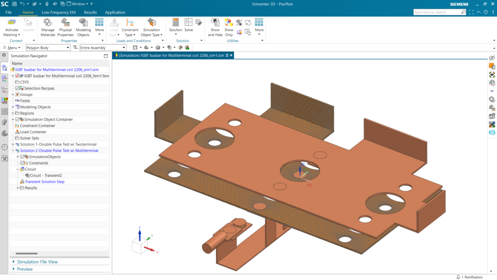
Inverters are types of power electronics modules. Power electronics handle electrical power conversion, typically using solid-state switching via power semiconductors such as insulated-gate bipolar transistors (IGBTs) and metal-oxide-semiconductor field-effect transistors (MOSFETs). For a small aircraft, the e-motor is 400 kW to 1 MW, and for a business jet-size aircraft, it is in the order of 2 MW (two 1 MW motors). For large aircraft, there are either several motors distributed over the wing or only a few with even more powerful motors. Just as a comparison, the Porsche Taycan Turbo S has 560 kW overboost power for a short period of time, its system voltage is 800 V which leads to a current of 700 A for such high power.
This means that, depending on the system voltage of the aircraft, there is a lot of power running through wires (also called bus bars) from the power source to the motors. There are typically two locations considered for power electronics:
- In the fuselage near the power source
- Mounted near or onto the motor
This would impact the method of cooling as well as the type of current running through the bus bars. If the inverters are in the fuselage, there would be AC running through the bus bars to the motors. If the inverters are near or on the motors, then DC is running through the bus bars. This will also have an impact on the bus bars and their cooling. There are even investigations on using cryogenic hydrogen (at approximately -250°C to -260°C, so just around 20K or 20°C above absolute zero) to cool the bus bars and therefore make them superconducting when using the right bus bar material. Such low temperatures also impact their surroundings if insulation is not properly done. The material in the vicinity can be negatively impacted on its durability.
AC bus bars will also generate a magnetic field and with that come a lot more thermal and electromagnetic challenges between the bus bars and their environment. Many can probably remember the older cars in which every phone call you would receive on your mobile would cause a staccato buzzing in your car radio speakers. This comes from badly insulated wires where the electromagnetic emissions from the phone induce currents that cause the speaker to buzz. It was a nice heads-up that your phone would soon be ringing!
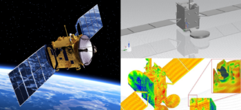
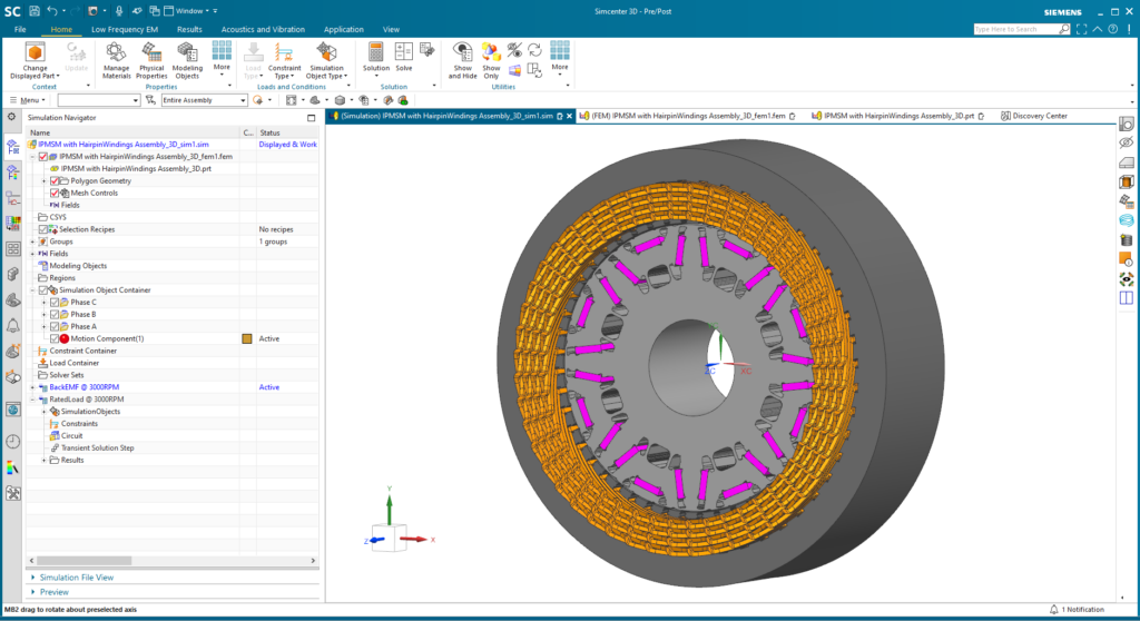
And not to mention the e-motor itself which needs to meet the requirements of the aerospace industry. It all starts with the design of the e-motor where there are many motor topologies to chose from. They all have advantages and disadvantages as every technology, so the right choice is left to the engineer and mitigate the disadvantages as well as possible with the help of detailed simulations to improve the design in the best way possible. This requires low-frequency electromagnetic and thermal simulations for motor cooling which might require looking into various ways of cooling methods.
But don’t we know power electronics well enough after all those years?
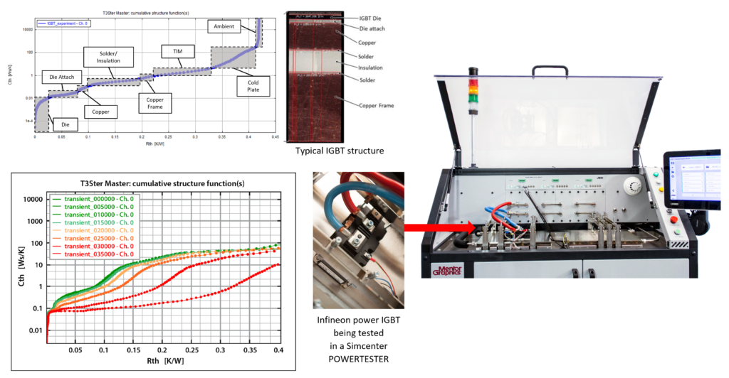
We do, and that’s exactly why we know that there is so much to consider for a proper and safe application, especially in aerospace. With Simcenter testing solutions, engineers can do power cycling of such power electronics, such as IGBTs and MOSFETs used in inverters. Such power cycling allows for aging tests by running through a lifetime of the component and measuring its thermal resistance and structure to see when and where the component will start to degrade due to the temperature fluctuations of its cycles. This can give important information on a component’s lifetime and where it fails, and it also helps to improve its design. Such thermal-structural impacts on the component can cause delamination of the layers of the semiconductor due to different expansion coefficients of the materials of the layers or the material degradation through aging, similar to a rubber band can become brittle from temperature variations. Thermal interface material (TIM) or other layers can also degrade. If you want to learn more about this, read this white paper.
Besides thermal effects, the electromagnetic interference (EMI) of such high-frequency switches has an impact on their design, their implementation in the power circuit and their environment. Just as mentioned with the car speakers, such interferences can cause malfunctions in the connected electronics of the system. Simcenter and Siemens EDA tools can simulate such effects to implement design changes early.
We might have known these components for a long time from applications such as the controllers of elevator motors, but we are facing way stricter rules and regulations on these components in aerospace applications. Engineers want to make sure they work optimally in a safe way and without impacting other components. Thermal, structural, EMI and other types of simulations need to be conducted while always paying attention to the testing side of things.
Then… Is it safe to fly with an electric aircraft?
It is as safe as flying any airplane. Engineers are working on making aircraft as safe as possible and Simcenter tools for simulation and test can help engineers to tackle these new challenges for a new era of flight.
You might be interested in…

Aircraft electromagnetic compatibility
Design advanced electrical and electromagnetic systems in the context of aircraft electrification
Bye Aerospace