Blocked Force Characterization on an Electric Motor: The stress of doing it right the first time

Getting your work right the first time is not an easy task, as our actions depend on experience and small errors can make a big difference in the results. Yet with an increasing amount of tasks and short deadlines, we are pushed to be both performant and precise and result oriented. This high-pressure environment is prone to errors. All this is not helping us engineers to do our work effectively.
We at Siemens are aware of this and therefore are striving to make your life easier and your work as straightforward as possible. I want to show you in this blog how you can use Simcenter Testlab to get accurate and precise results efficiently. Ideally, this blog inspires you for your next measurement campaign.
The test object: a small electric motor
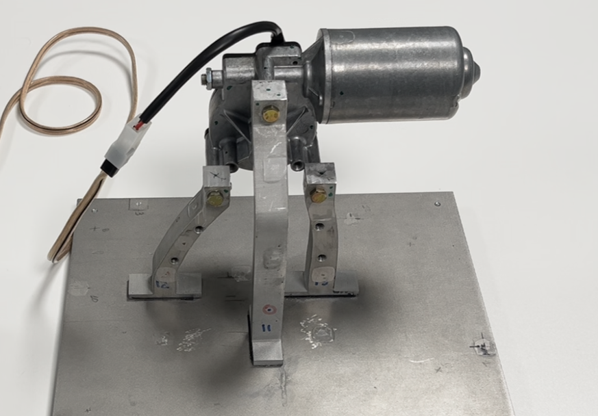
I have recently performed a characterization of our demonstrator, a small electric motor. I want to share my experiences with you. This small wiper motor demonstration test bench is representative of small noisy vehicle ancillaries, such as small e-motors, compressors, and pumps. Here it is:
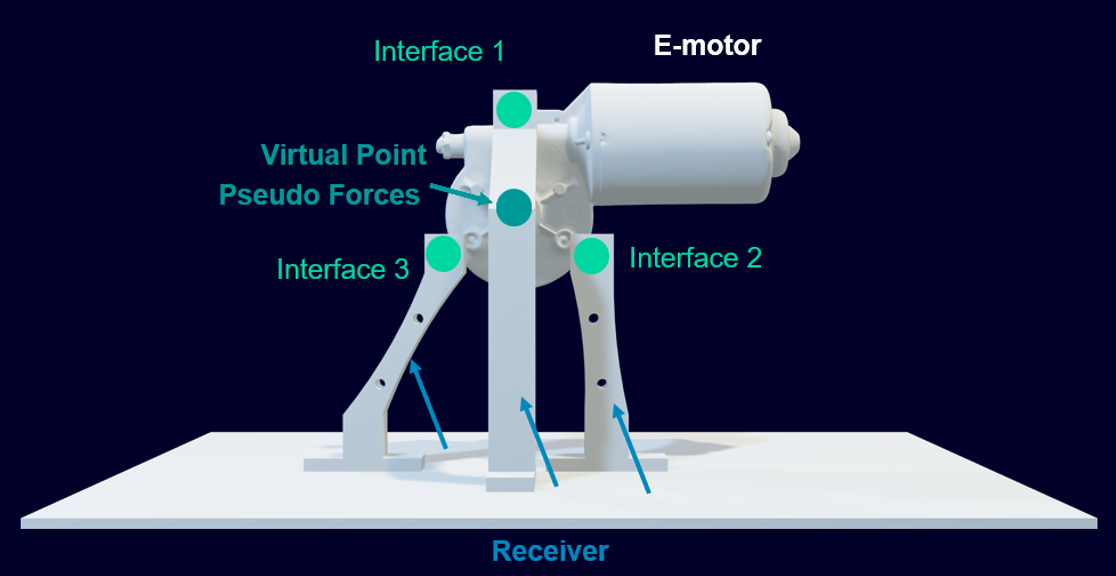
We will characterize this component with pseudo forces. Now you might tell me that you wanted to see a blocked force characterization. And yes, pseudo forces are a kind of blocked forces, but they are not directly derived from the interface points, but from other locations of the test object. In our case, this is a Virtual Point in the center between the interface points. See my image below:
These pseudo forces can afterwards be used in the same manner as blocked forces. For example, you can use them with Frequency Based Substructuring to create virtual assemblies, or they can be transferred into the interfaces with transfer FRF (Frequency Response Functions). While this won’t be demonstrated in this blog, it provides context for what you can do with pseudo forces. If you want to know more about this, please contact us.
Why do we use pseudo forces?
Simply because we will identify fewer unknowns (3 translational forces and 3 torques) than if we identify blocked forces at the interfaces. For small components like compressors, pumps, or electric motors, this is a very beneficial approach. We will be more accurate in the low frequency range.
How do we measure pseudo forces?
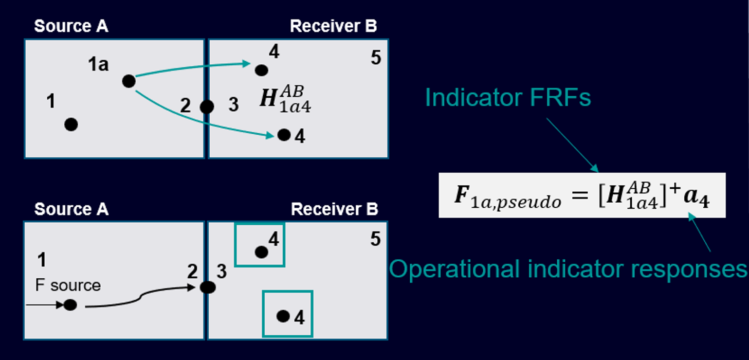
We measure them with the In-situ TPA (Transfer Path Analysis) approach. This is a well-known method, a two-step approach where we first measure the indicator FRFs and in a second step the operational indicator response. We can use the formula below to derive the pseudo forces at our virtual point:
Let’s start now with the measurements!
But wait, first let us do the virtual instrumentation. Let me go through each step by highlighting the important points for you. Here are the different steps towards characterizing a component:
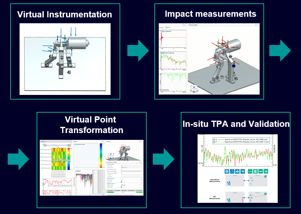
Virtual instrumentation
Before starting to measure right away, let us properly prepare our task with virtual instrumentation. For that, we will use a CAD model of the test object. In my example, I have scanned the electric motor and imported the *.step file into Testlab. The receiver has been modeled with standard CAD software Siemens NX.
Why is it important to prepare our measurements? Because we need to place our impacts in a manner that excites all our coordinate directions in a similar way. How can we do this? Here are the different steps:
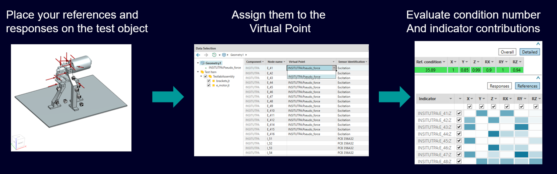
Indicators snap automatically to the CAD model, thanks to the CAD support, and complex geometry is easily created. Finally, condition numbers and sensors sensitivities indicate which coordinate direction needs improvement.
The demonstration video below illustrates the key advantages of a proper CAD Instrumentation preparation:
- Evaluate available space
- High precision sensor positioning
- Prepare the right position and number of your indicators ahead of the measurement
Impact measurement – with Simcenter Testlab Neo a ONE person job
The new Simcenter Testlab Neo Impact Testing workbook will guide you step by step through the data acquisition workflow. The key highlights of the impact testing are:
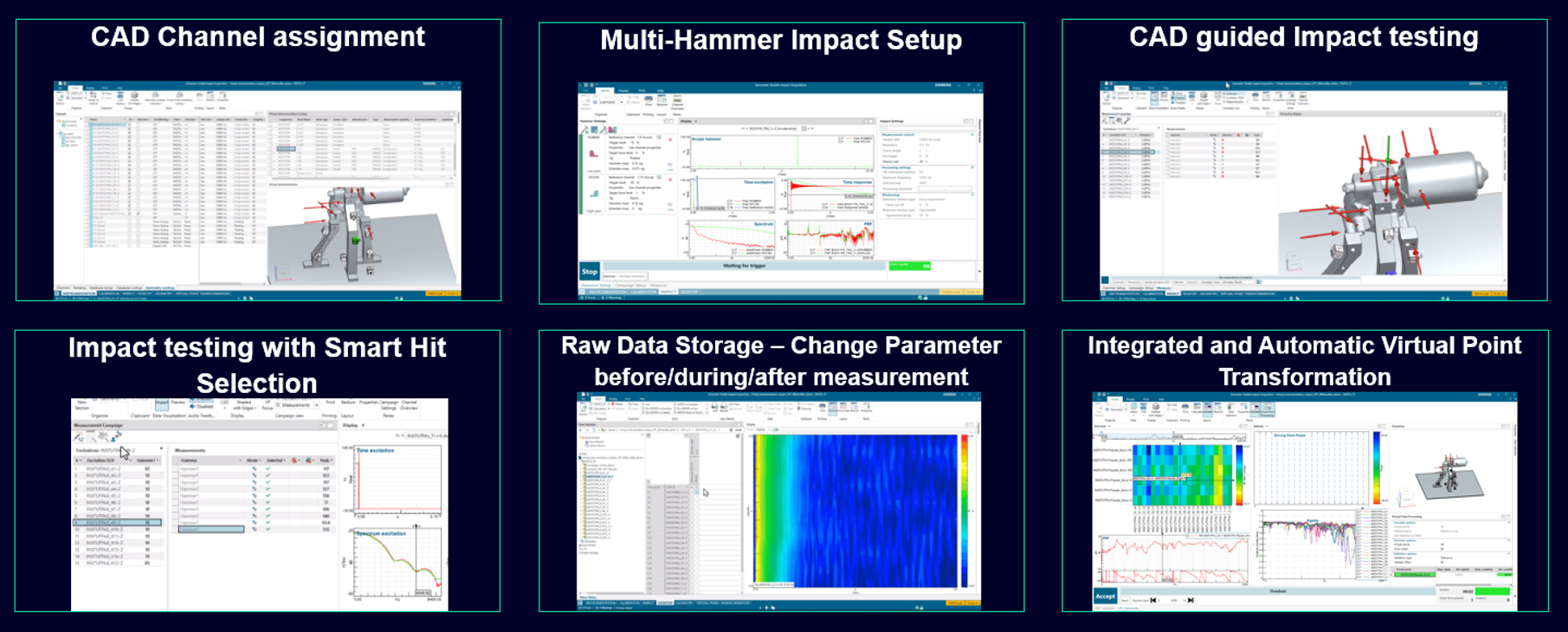
Some more details about each step:
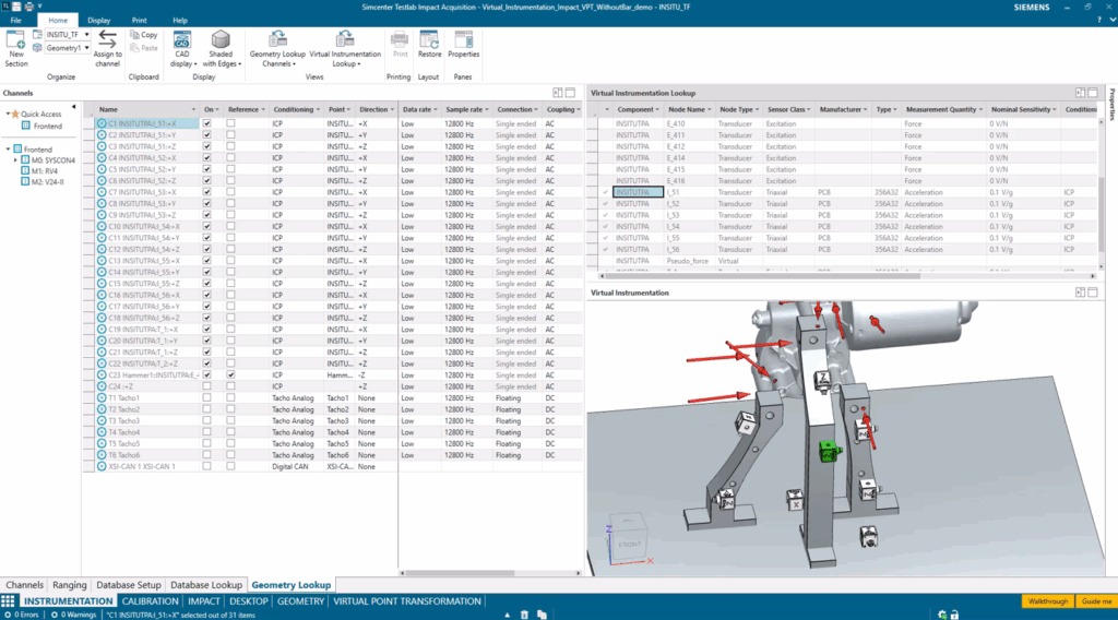
CAD channel assignment and instrumentation of the test object
In this step, you will instrument your test object and link the virtual channels to the real channels.
The hammer setup
The hammer setup supports multiple hammer tips including automatic merging of both impacts. This enables us to measure the entire frequency range. The transition frequency between the two hammers is user defined and can be changed any time, even after the result storage.
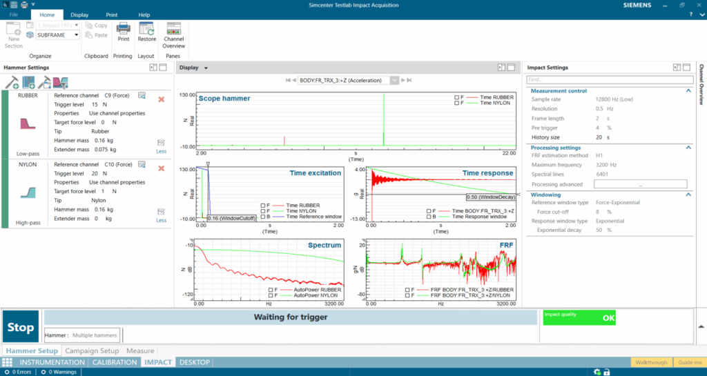
The impact measurement
During the impact measurement, we will impact at different positions to excite the structure. This process is CAD guided, which makes it very easy to identify where to hit next. Smart Hit Selection is one of the key capabilities for an efficient and precise result. It automatically selects the best impacts during or after the measurements. Once you have done all your impacts, a simple glance at the overall indicator is sufficient.
Saving your results
Once you are done with your measurements, you will save the project and the results. Want to change any setting, like Multi-hammer filter, output storage choice, or hammer windowing? We are backing you up: You can change settings and save again or even reopen existing projects! The raw data of our impact measurements are stored, so you can make any changes and save your results again.
Virtual point transformation
Now you can derive your impedance FRFs. Have you stored your FRFs and coherences? You are a few clicks away from your indicator FRFs. Automatically select the best references to increase drastically your valid frequency range.
In the video below, you see the few steps you must take to get the references transformed into your virtual point.
You might ask what the key criteria are for a successful VPT (Virtual Point Transformation)? Here Testlab helps you; in fact, it automatically considers the overall condition number of the transformation matrix, and it will increase the overall rigidity indicator by selecting the best impacts.
In-situ TPA pseudo force calculation and validation
Have you already used our new In-situ TPA calculation tool in Testlab Neo? Here it comes! Since Simcenter Testlab 2506, we have TPA in Testlab Neo with matrix inversion. This is perfectly what we need to do this analysis and additionally it is very efficient to get the results.
Here are two small videos that show you almost the entire steps to get your results.
First I need to define my TPA model.
Second I need to calculate the results.
Conclusion: Transforming your testing process
As engineers, we’re constantly balancing the need for accuracy with ever-tightening deadlines. The innovations in Simcenter Testlab that I’ve shared demonstrate how technology can help us achieve both goals simultaneously. By integrating virtual instrumentation with intuitive workflow guidance, what was once a complex, error-prone process evolved into a more streamlined, single-operator procedure.
The benefits of this approach extend beyond mere convenience:
- Enhanced Accuracy: The Smart Hit Selection and automatic reference selection ensure optimal data quality throughout the measurement chain
- Significant Time Savings: CAD-guided impact testing and efficient workflow reduce measurement campaign duration
- Increased Confidence: Real-time feedback on measurement quality helps ensure you get it right the first time
- Future-Proof Results: Raw data storage means you can revisit and refine your analysis as needed
Efficient, isn’t it? Let us know what you think about it.
Need more information?
Contact my colleagues or myself – we are here to help you.
Interested in our free webinars about component-based TPA or virtual assemblies?
- Predict vehicle NVH performance | Siemens Software
- Component-based transfer path analysis | On-demand webinar | Siemens Software
C-TPA Masterclass
Join us in November 2025 to master the transition from physical testing to virtual prototyping with hands-on workshops, expert-led sessions, and exclusive insights into our new technologies. Perfect for NVH engineers looking to stay ahead in the age of electrification!