Intercax brings System Modeling Language to NX

A common challenge in developing complex systems (one involving the application of three or more engineering disciplines in its development, e.g. mechanical, electrical, and software engineering) is integrating requirements with mechanical design. When requirements governing system geometry are in text form, they are often easy to misinterpret. Sketches and other images may be simpler, but they are not model-based. Our objective is to pass requirements to the design engineer in a clear, model-based way, as a native computer-aided design (CAD) file that can become the starting point for the mechanical design.
As a Siemens Software and Technology partner since 2012, we have worked closely with Siemens engineering software users in the automotive and aerospace industries at the leading edge of model-based engineering.
An example of using system modeling language
Syndeia, the model-based systems engineering (MBSE) interoperability platform from Intercax, provides a practical approach to building a digital thread connecting requirements to architecture and design. In this example, we will use Syndeia to transform a Systems Modeling Language (SysML) architecture model in Cameo System Modeler (CATIA NoMagic) into a CAD model in Siemens NX.
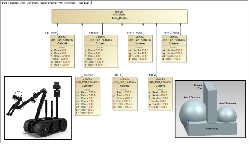
We will consider an unmanned ground vehicle (UGV), a small multi-purpose robot (see inset in Figure 1) with two arms: a front arm configured as a multi-axis manipulator, and a movable rear arm holding sensors, such as a high-resolution video camera.
Syndeia enables model transform of SysML block structures to a Siemens NX CAD file in a precise way. Figure 1 shows part of the SysML model. The part properties of the top-level block, Arm_Reqts, are usages of a limited set of geometric primitives (e.g., Cuboid, Sphere) that Syndeia recognizes and can create as part features in an NX CAD file. These have a set of characteristic value properties that define the origin, orientation, and size of the element. The part property names represent the role that element plays in the requirement.
For example, the part property ugv_body represents a cuboid robot body with a length of 800 mm, the width of 600 mm, and height of 200 mm. The arm_1_locus: Sphere represents the required range of motion of the front arm, with an origin of (150, 400, 50) and a diameter of 500 mm, representing a maximum extension of 250 mm from the mounting point.
Clearly, the UGV body is a region the arms cannot penetrate. Similarly, keepout_1:Cuboid represents a region between the two arms that neither of the arms is allowed to infringe upon to prevent interference between the arms. Its position is clearly defined with respect to the rest of the assembly and affects both the static and dynamical aspects of the mechanical design.
The resulting 3D parameterized CAD file is shown as an inset in Figure 1, with labels added for clarity. Note that the spheres representing the arm extension overlap with the keep-out zone as well as the UGV body, requiring either a mechanical or control solution to prevent interference. This CAD model becomes the starting point for the mechanical designer’s work, defining the size and relative position of critical structural constraints.
About the Author
Dr. Dirk Zwemer is President of Intercax LLC, a supplier of MBSE engineering software platforms such as Syndeia and ParaMagic. He is an active teacher and consultant in the field and holds Level 4 Model Builder-Advanced certification as an OMG System Modeling Professional.
About Intercax
Intercax is an innovator in the field of engineering software for building the Digital Thread, enabling engineers, software developers, and managers to find the information they need quickly and control cost, schedule, and quality in the development of complex systems for aerospace, automotive and defense applications. Intercax has been a Siemens Digital Industries Software Software and Technology Partner since 2012. Software and Technology partners are leaders in their domain and leverage the open Xcelerator portfolio to provide customers with a comprehensive set of integrated solutions.
Links and References
Videos and tutorial exercises for SysML-NX
Bajaj, M., Cole, B., Zwemer, D. (2016). Architecture to Geometry Integrating System Models with Mechanical Design. AIAA Space 2016 Conference, Long Beach, CA, USA, Sep 13-16, 2016


