Boost simulation results with powerful selective net extraction with Calibre xACT
By Karen Chow
In advanced integrated circuit (IC) design, post-layout parasitic extraction is crucial for accurate performance analysis and optimization. In modern designs, simulation efficiency and data manageability are more important than ever. While comprehensive, full-chip parasitic extraction is often required for signoff, it may not always be practical—especially when engineers need to focus on performance-critical paths or when computational resources are limited.
Selective parasitic extraction using Calibre xACT lets engineers generate extracted netlists containing only user-specified, performance-critical nets. This targeted extraction can dramatically improve simulation speed and efficiency, streamline debugging and enable finer-grained design optimization. In this blog, we outline the methodology, discuss configuration options and walk through a practical workflow for extracting parasitics on selected nets using Calibre xACT.
Benefits of creating parasitic extraction netlists with particular nets
Creating parasitic extraction netlists with particular nets—rather than extracting parasitics for the entire design—offers several strategic benefits, especially in complex or high-performance integrated circuit (IC) designs. Here’s why this targeted approach can be a game-changer:
- Improved simulation efficiency
Reduce the size of the netlist by extracting parasitics only for critical nets (e.g., clock, power, high-speed data lines). Smaller netlists mean faster SPICE simulations and less memory usage. - Focused accuracy
Apply high-accuracy extraction methods (like 3D field solvers) to sensitive nets while using faster, less detailed methods elsewhere. This hybrid approach balances precision and performance. - Better debugging and analysis
Isolating parasitics on specific nets helps pinpoint signal integrity issues like crosstalk, delay or power or noise issues. Designers can more easily correlate layout features with electrical behavior. - Design optimization
Minimize parasitic effects on performance-critical paths with targeted tuning of layout parameters (e.g., wire width, spacing). This helps meet timing, power and noise budgets more effectively. - Scalability for large designs
Reduce the burden of full-chip parasitic extraction for large SoCs or memory arrays. Selective net extraction allows hierarchical or modular verification without overloading simulation tools. - Reduced risk of over-extraction
Avoid unnecessary parasitic data that can clutter the netlist and lead to misleading simulation results or longer runtimes.
When to use selective extraction
Selective extraction is especially useful in cases where specific nets play a critical role in overall circuit performance. For example, extracting parasitics from clock trees helps engineers ensure timing closure and minimize jitter, which is vital for reliable operation in synchronous designs. In power delivery networks, targeted extraction allows for detailed analysis of IR drop and electromigration, supporting robust power integrity across the chip. High-speed interfaces also benefit from this approach, as signal integrity and impedance matching are essential to maintaining data fidelity at elevated speeds. Finally, analog blocks are particularly sensitive to parasitic effects, so focused extraction in these areas enables more accurate simulation and optimization of performance parameters.
How to use Calibre xACT to extract particular nets
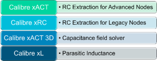
Calibre xACT is a high-performance parasitic extraction tool designed to deliver accurate and scalable modeling of parasitic effects in integrated circuit (IC) designs—especially for advanced nodes and large-scale chips.
Bonus content! We have a technical paper with more information on this topic “Parasitic extraction technologies for advanced node and 3D-IC design”
What does Calibre xACT do?
Calibre xACT calculates the resistance (R), capacitance (C) and inductance (L) of interconnects and devices in your layout, which are critical for:
- Timing analysis
- Signal integrity
- Power integrity
- Electromigration checks
These parasitic elements can significantly affect circuit behavior, especially in high-speed or low-power designs.
Sample design: operational amplifier
An operational amplifier, or op-amp, is an electronic component used to amplify voltage signals. It’s one of the foundational building blocks in analog circuit design. Here is the schematic of our opamp:

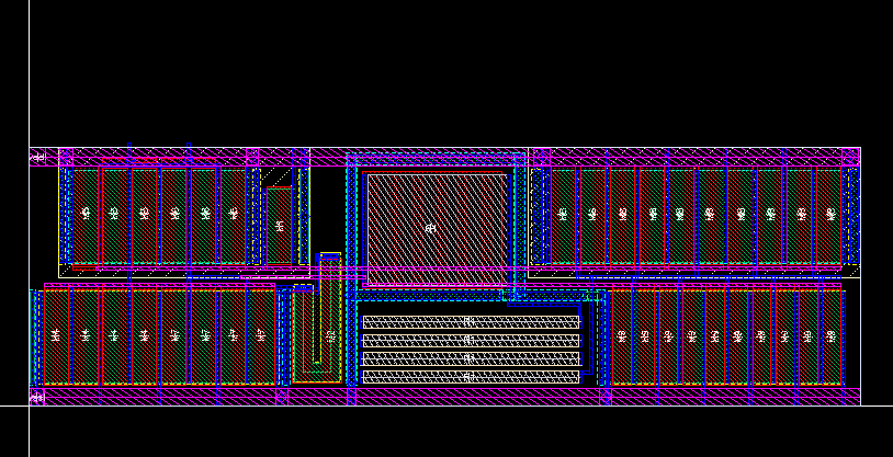
We then created a layout from this schematic. Layout is a fundamental step in IC design, where you translate your circuit diagram into a physical representation that can be fabricated.
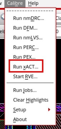
To run Calibre xACT for this sample design, select the Run xACT option in the Calibre menu:
This will launch the Calibre Interactive graphical user interface (GUI), which simplifies the setup and execution of parasitic extraction tasks.
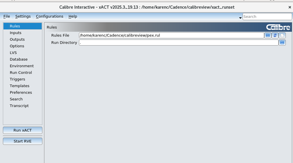
The first page in Calibre Interactive is Rules. This is where you add your top-level SVRF rule file that includes your LVS and xACT rules from the foundry.
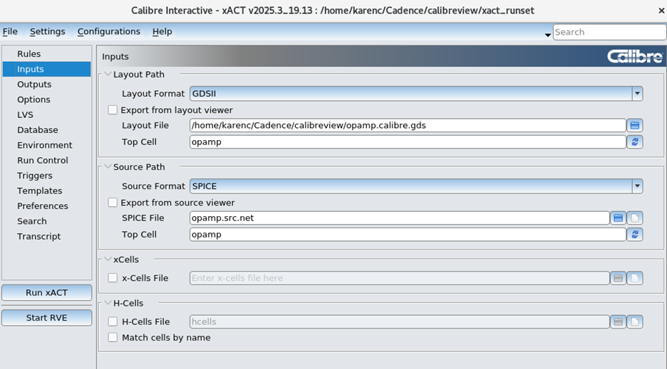
The Inputs page is where you specify the name of the cell that you are working on and whether you want to stream out the GDS file from the layout (for example, if you have modified the layout), or whether you want to use the GDS file already created. For Source Path, you can select whether you want the netlister to create a new netlist from the schematic if you have made changes, or whether you want to re-use the old netlist because you have not modified your schematic.
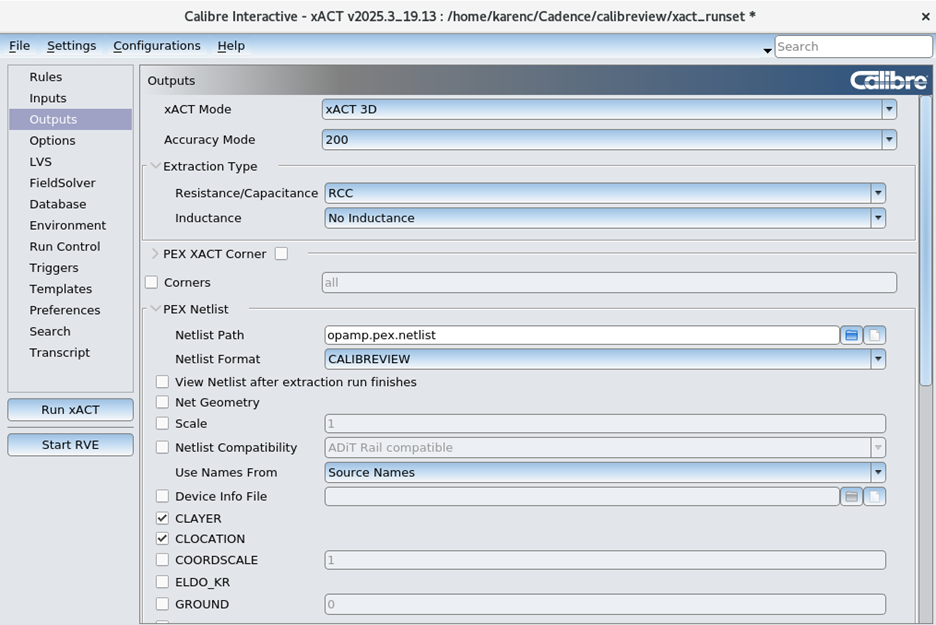
The Outputs page is where you specify the output format of the extracted netlist. For the xACT Mode, you can specify xACT for faster parasitic extraction, or xACT 3D if you want high accuracy 3D field solver accuracy. In the PEX Netlist section, you can specify which netlist format you want, for example, DSPF, Hspice, or the Cadence CALIBREVIEW extracted view format, which is what we use in this example.
Use names from: Layout names vs. source names
For the extracted netlist, net names can be taken either from the layout (for example, an annotated GDS file), or from the schematic, using layout vs. schematic (LVS). For calibreview flows, it is best to use names from the schematic. If layout names are used, the extracted view will only have net names that have been annotated and all of the other nets will get a random number, like 1, 2, 3, etc.
For extracted view flows, since the test bench will be plotting points with the real net names and not 1, 2, 3, etc, then a source name should be used.
There are three different formats for source name flows:
- SOURCENAMES: Specifies the names are derived from the schematic or netlist, but the hierarchy is based on the layout.
- SOURCEBASED: Specifies to use the circuit pin order and cell hierarchy in the source netlist instead of the layout netlist when generating the extracted netlist.
- SCHEMATICONLY: Specifies a parasitic netlist based on the LVS source hierarchy, with intentional device parameters extracted and backannotated from the layout. Parasitics are netlisted only for nets that are cross-referenced to the source netlist. If filename is not used, only standard parameters for MOSFETs are backannotated. Other devices use source parameters.
In our example, the source netlist will have:
MM9 VO net054 vss! vss! N W=15u L=3u M=10
This is an nmos device (N) with 10 fingers (M=10).
The most commonly used flow is SOURCENAMES, because the parasitics between each finger of the device will be captured because each finger is individually netlisted.
SOURCENAMES
For SOURCENAMES, Calibre LVS will find 10 individual nmos devices and know that they are all connected together. In the Calibre xACT netlist, if SOURCENAMES is selected, there will be 10 individual devices and all of the post-layout LVS device properties will be measured.
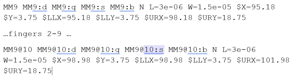
The parasitics between each of these 10 fingers, for example, in the polysilicon, will be captured in the parasitic netlist.
SOURCEBASED
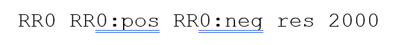
In sourcebased flow, the devices will only be netlisted as one device, copied directly from the source.

And our designed resistor is copied directly from the schematic:
SCHEMATICONLY
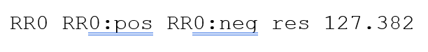
In schematiconly flow, the device is also collapsed into one transistor with M=10

The designed resistor is measured from the layout:
What options should Calibre xACT use for extracted view
For the calibreview format, the options we use in this example are Net Geometry, CLAYER, CLOCATION, LOCATON, RLAYER, RLENTGH, RLOCATION and RWIDTH.
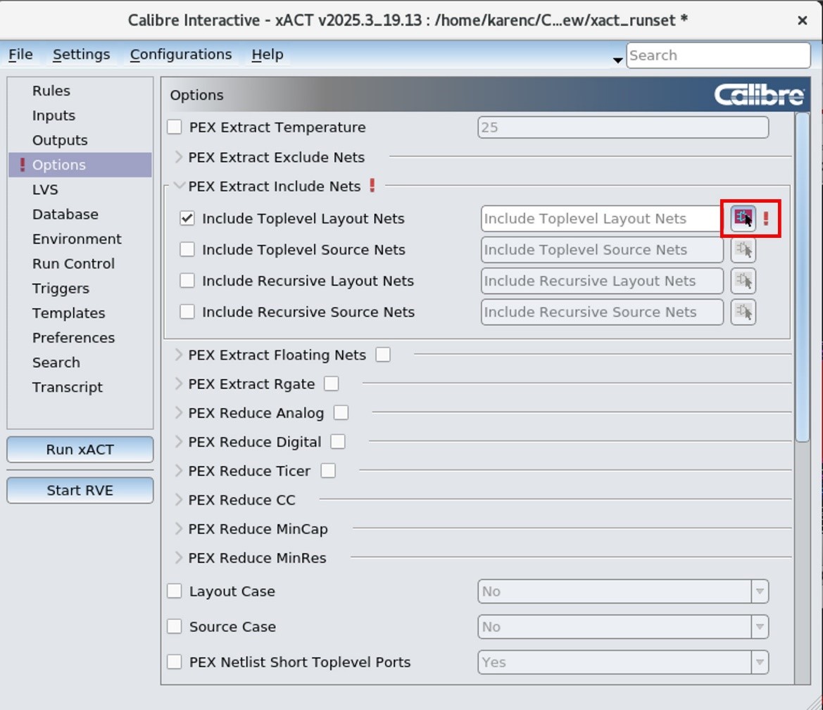
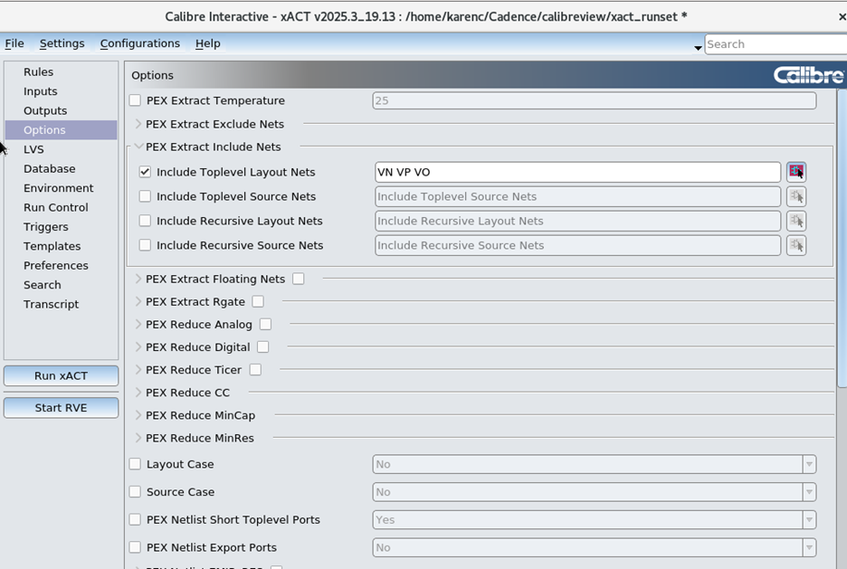
In the Options page, you can select which nets to include in the selected net extraction run. Click the select icon to select the critical nets in the schematic:
Then in the schematic, select the critical nets.
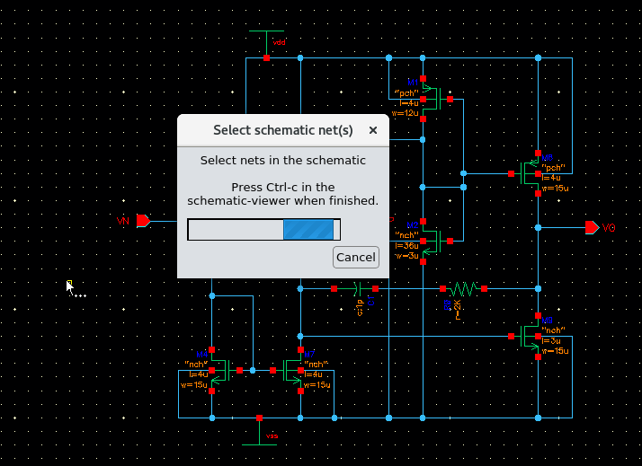
Press Ctrl-c when done. The three selected nets will then be populated in Calibre Interactive:
Click Run xACT to run Calibre xACT. When the extraction is finished, a new window will appear for Calibre view setup.
Calibre view setup
The Calibre View Setup window lets the layout editor know where each of the devices reside in the Cadence library and which library should be used for the parasitic devices. In this example, we use analogLib for the parasitic resistors and capacitors.
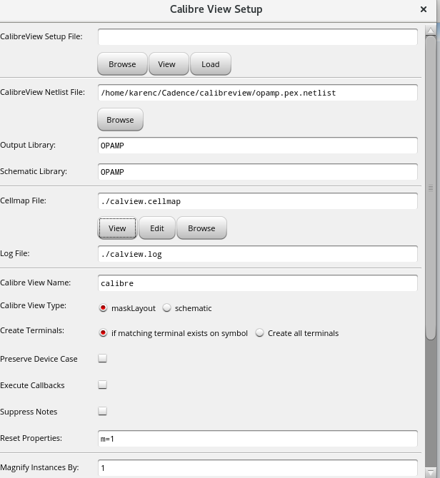
The Cellmap File is a listing of the designed devices and parasitic devices and how the parameters should be mapped between the Calibre xACT netlist and the Cadence library. This cell mapping file is provided by the foundry.
The Calibre View Name is the name of the extracted view that will show up in the Cadence library. Users may choose to run extraction multiple times and can store multiple extracted netlists with different names, for example, calibre_selectednet, calibre_allnets, calibre_noreduction, calibre_withreduction.
The Reset Properties field is for resetting the name of the multi-fingered device, so instead of copying the value for NF or mult from the schematic, each of the fingers should be set to 1.
Click OK.
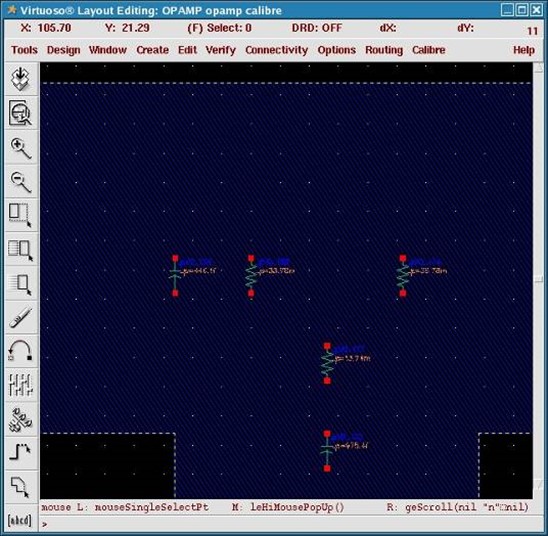
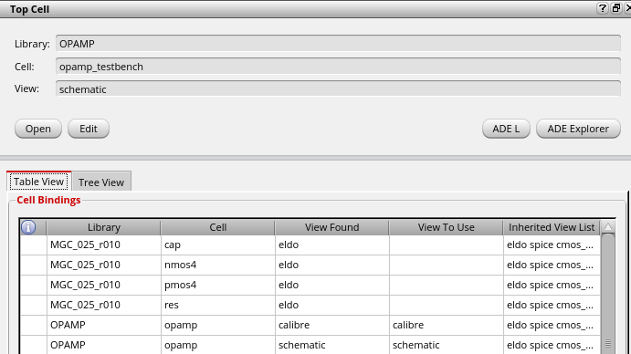
A graphical calibreview will be created, with parasitics only on the critical nets that were selected. This extracted view can then be used within the Analog Design Environment (ADE). Either all instances of the opamp can point to the newly created calibre view, or you can use the Hierarchy Editor to point specific instances to the calibre view and others to the original schematic:
Summary
We present the advantages of selective parasitic extraction and the methodology for performing it using Calibre xACT. Targeted extraction improves simulation efficiency, enhances accuracy for sensitive nets, simplifies debugging and scales better for large designs like SoCs. It’s especially useful for clock trees, power delivery networks, high-speed interfaces and analog blocks.
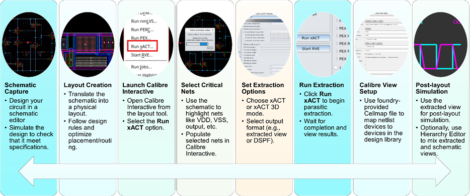
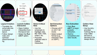
The article walks through a practical example using an operational amplifier (op-amp) design. It details how to:
- Capture the schematic and create a layout
- Use Calibre Interactive to configure extraction settings
- Select specific nets for extraction
- Generate a calibreview format netlist for use in Cadence ADE
The result is a graphical extracted view containing parasitics only on selected nets, enabling precise and fast analysis and optimization.
FAQ: Selective parasitic extraction with calibre xACT
1. What is Calibre xACT?
Calibre xACT is a high-accuracy parasitic extraction tool from Siemens EDA. It calculates resistance (R), capacitance (C) and inductance (L) of interconnects and devices in IC layouts, enabling precise timing, power and signal integrity analysis.
Watch our quick video to hear more
2. Why extract parasitics for particular nets instead of the whole design?
Selective extraction:
- Speeds up simulation by reducing netlist size
- Focuses accuracy on critical nets
- Simplifies debugging and layout optimization
- Scales better for large designs like SoCs
3. Which nets should I extract parasitics for?
Target nets that are performance-critical or sensitive to parasitic effects:
- Clock trees (timing closure)
- Power delivery networks (IR drop, EM)
- High-speed interfaces (signal integrity)
- Analog blocks (precision performance)
4. What is Calibre Interactive and how does it help?
Calibre Interactive is a GUI that simplifies the setup and execution of Calibre tools. It lets you:
- Load rule decks
- Select specific nets
- Configure output formats
- Launch parasitic extraction jobs with ease
5. How do I select specific nets for extraction?
In Calibre Interactive:
- Use the Options tab
- Click the Select icon
- Highlight critical nets in the schematic
- Press Ctrl+C to populate them into the extraction setup
6. What output formats are supported for Calibre xACT extracted netlists?
Calibre xACT supports:
- DSPF
- HSPICE
- SPEF
- SPECTRE
- ELDO
- CALIBREVIEW
7. What is calibreview and how is it used?
Calibreview is a graphical extracted view format generated by Calibre xACT that is compatible with Cadence tools. It allows simulation of extracted parasitics within ADE.
8. What is the Cellmap file and why is it important?
The Cellmap file maps parasitic devices to Cadence library components (e.g., analogLib). It ensures correct interpretation of extracted parasitics during simulation and is typically provided by the foundry.
9. Can I run multiple extractions with different settings?
Yes. You can create multiple extracted views with different names like:
- calibre_selectednet
- calibre_allnets
- calibre_withreduction
- calibre_noreduction
This allows flexible simulation and comparison.
10. How do I use the extracted view in simulation?
In Cadence ADE:
- Point instances to the extracted view using the Hierarchy Editor
- Or set all instances in the Switch View list to use the calibre view for post-layout simulation
11. When should “SOURCEBASED” and “SCHEMATICONLY” options be used for calibreview?
SOURCEBASED or SCHEMATICONLY should be used when simulation time is too long and you want the post-layout extracted netlist to not show the individual fingers of a multi-fingered device. All parasitics between the fingers will be ignored.
12. When should “SOURCENAMES” option be used for calibreview? SOURCENAMES should be used for calibreview when the highest accuracy is needed, because the parasitics between all of the fingers of the device will be captured.