Automated Chip Polishing Can Make Your Design Shine
By Bill Graupp, Mentor Graphics
A more robust design creates a more reliable product, and reduces yield variability over its life cycle.
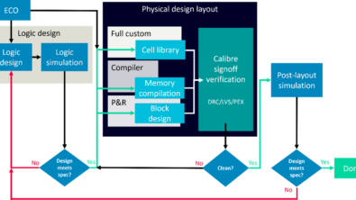
Today’s modern chip design is a collaboration among many design teams, often using different design flows and different EDA tools. This state of the chip design industry can create high risk in the layout process, forcing delays in product release. To help reduce this risk, many levels of verification throughout the design flow exist to identify problematic areas in a design. While new EDA tools have been developed to automatically correct or remove many design rule violations, some non-DRC violations can still cause susceptibility to manufacturing issues, and lead to delays in manufacturing prototypes.
For example, designers creating the top-level chip layout can construct regions of interconnect that have rough edges along signal and power lines. Multiple IP vendors delivering blocks to the final chip team can cause misaligned pitch during block alignment. Routers connecting metal pins with slightly different metal widths than the IP block can cause small jogs. Insertion of via doubling cells can cause line end T’s. Mushroom-shaped structures can cause difficulty in mask generation. Offset via placement in metal overlap regions can create poor coverage issues during manufacturing.
Even though none of these layout issues are design rule errors, they can still lead to problematic designs. Finding and eliminating layout issues such as nano-jogs, space ends, mushrooms, dog bone ends, and offset vias creates a more robust design that is less prone to yield variation, leading to faster time to prototype manufacturing.
Design for manufacturing (DFM) tools like Calibre YieldEnhancer are implementing automated analysis capabilities that assist designers in evaluating a design for these types of issues, and in calculating the changes that can be applied to improve manufacturability. Programmable Edge Modification (PEM) commands can improve a layout by automatically analyzing a design, then smartly removing or altering the offending edges. These PEM commands use measured edge properties to characterize the layout region, then calculate the best possible edge movement to improve the layout. This final stage of design review is often known as “chip polishing.”
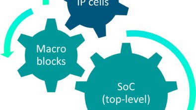
Many of the issues that require or benefit from chip polishing arise from hierarchical issues, such as two lines from two cells being connected at the parent cell without the knowledge of the entire line shape or width. Other typical problematic layout features include:
- Space Ends – Metal lines formed into a “J” due to the router passing a short adjacent track line and coming back to far end. The connection bottom of a “J” can pinch if the loopback is too narrow.
- T-Line Ends – Metal lines with a narrow cross “T” at the end can cause necking.
- Mushrooms – A long metal line connected to the center of a short metal adjacent track line typically causes necking of the connection metal.
- Nano-jogs – When two metals of slightly different widths are connected end to end, it creates breaks in long edges that cause unnecessary run time in verification and mask generation.
- Offset Vias – Manually-placed vias at an adjacent metal overlap that are not centered in the overlapping region create potential via coverage issues that can cause higher electrical resistance.
PEM commands include a variety of programmable adjustment options to correct these types of design issues:
- Polygon shifting
- Polygon sizing
- Edge-based polygon creation
- Feature-based edge identification (jogs, space ends, etc.)
- Polygon growth with spacing considerations
Creation of a custom Calibre PEM flow is not difficult, and the runtime is minimal, especially compared to the time it can shave off the chip finishing process. Normally, a designer using the Calibre YieldEnhancer product polishes the block or chip layout after completing via enhancement, and prior to creating fill for the layout. A typical automated PEM flow fixes nano-jogs and notches first, followed by filling space ends, and ending with line end adjustments and isolated line width widening. A hierarchical-based flow will generally achieve the best design integration.
By reducing the number of edges in the design through chip polishing, many chip release tasks can be improved or eliminated. It’s only logical that mask generation can optimize long edges more quickly when they do not contain jogs or notches, so it’s no surprise that final verification runtimes for large blocks and chip layout can be reduced by eliminating any edges broken into fragments due to accidental jogging. Mask generation is also faster due to the optimized line ends, meaning there are fewer edges that will require optical proximity correction (OPC). By having a faster mask flow with fewer issues to manage, the manufacturing process can be optimized for the consistency of the manufacturing models used to control the process. A more robust design will also create a more reliable product, as well as reduce yield variability over the life cycle of the product.
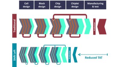
Design integration of today’s large and highly-integrated SOC chips can benefit from the application of automated polishing tools. Enhancing the robustness of your design and shortening the prototype turnaround time are key components of the final design cost. A well-designed automated PEM flow can improve your product’s manufacturability, allow you to get to market faster, and enable you to create market differentiation.

Liked this article? Then try this –

This article was originally published on www.semiengineering.com