Balancing on the Color Density Tightrope
By David Abercrombie
Potential pitfalls and available solutions.
Balancing on wobbly tightropes is something that chip designers get pretty good at. For instance, there is a fine balance between optimizing performance and minimizing leakage in a design layout. Dealing with the new requirements that multi-patterning (MP) introduces into a design flow creates many new tightropes to walk. I tiptoed out on one of the rarely talked about ones in my last article—density requirements. Let’s take a deep breath and step right out to the middle.
Now, density requirements aren’t a new thing, right? We all know that overall pattern density and density uniformity affect the results of lithography, etch, chemical-mechanical polishing (CMP), rapid thermal annealing (RTA) temperature uniformity, stress, etc. So, for many technology nodes now, there have been density rules that must be met during design rule checking (DRC). The traditional solution to meeting these density requirements is the use of dummy pattern fill. Extra, non-active design shapes are inserted into open areas of the design to smooth out the density variation across the layout. Over time and nodes, the increasing stringency of density requirements has led to the development of more and more “smart” filling applications to help designers meet those requirements. However, this fill has pretty much been something that could be dealt with after the fact of the active circuit design—essentially just a post-processing step in the design flow.
Multi-patterning introduces a whole new level of density requirements because a given design layer is actually processed as more than one mask and etch step during manufacturing. The pattern defined by each mask not only has to be uniform by itself, but it also has to have comparable density to the other mask(s) for that layer. To simplify the concept, let’s think about a double-patterned litho-etch-litho-etch process application in which a given design layer will be decomposed into two colors (i.e., two masks). There are potentially three types of density requirements related to such a layer that you might encounter in DRC.
- Each color might need to meet certain total density and density uniformity requirements individually.
- The density ratio between the two colors may need to meet certain uniformity requirements.
- The combination of the two colors may need to meet traditional total density and density uniformity requirements.
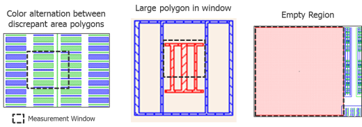
Let’s focus our discussion on the second requirement—uniformity of the density ratio between the two colors in such a double-patterned process. At first glance, it seems very simple. You draw the needed active circuit design shapes, and then assign half of them to one color and the other half to the other color. But of course, it can’t be that easy, and Figure 1 shows examples of failing density ratio failures in real designs.
Figure 1: Density measurement windows that fail due to discrepancies in polygon areas.
Not every polygon in your design has equal area, so simply dividing them in half and arbitrarily assigning each half to one of the colors does not necessarily produce an even distribution. Some polygons may be so big that they completely or nearly completely encompass an entire density window region. If this polygon is simply assigned to a single color, that density window will fail. If the density window includes just a single polygon from the active design that is a single color, that window will fail. If you don’t add and color dummy fill in an empty region, then the windows overlapping that empty region may fail for having no color. Off the tightrope you go!
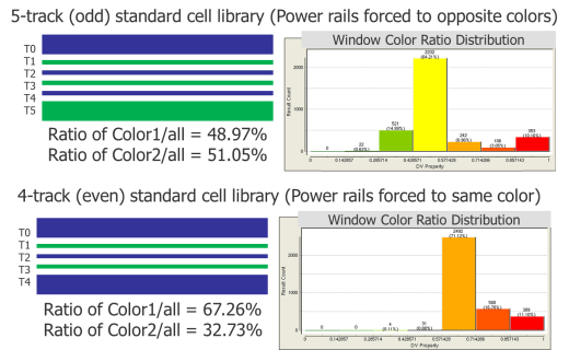
Even early design methodology decisions can have a dramatic effect on the final color density balancing. Figure 2 shows how the standard cell track height can make a difference. The choice of the number of tracks in the standard cell library inherently impacts the required coloring of the power rail tracks, due to the color alternation requirements between neighboring tracks. An odd number of tracks forces the power rails to be opposite colors, while an even number of tracks forces the power rails to be the same color. Because the power rails are typically much wider than the signal tracks, they dominate the area influence on color. The histograms of the density windows show a significant offset in the color ratio on the design in which both power rails are the same color.
Figure 2: Different standard cell track heights can affect the color density ratio in a large standard cell design block.
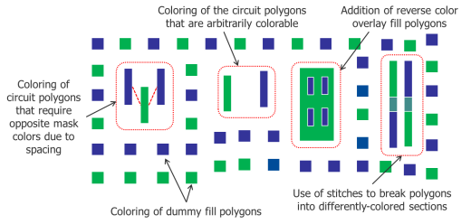
The actual density ratio between the two colors in any given window region is influenced by a number of factors, depending on the various design options your foundry may support in double patterning. Figure 3 demonstrates some of these factors.
Figure 3: Design constructs that contribute to the density balance between the two colors in a double-patterned process.
Most of the active circuit design polygons in advanced node designs are at minimum space to reach maximum design compaction. This tight spacing requires neighboring polygons to alternate coloring for the shapes to be successfully manufactured. This restriction means that, irrespective of the area of each individual polygon, these densely spaced polygons are forced to alternate colors, regardless of whether it helps or hurts the color balancing.
Some percentage of the active circuit design polygons are not at this tight spacing. These polygons can be arbitrarily colored as needed to suit a density-friendly distribution. However, depending on the design flow, their coloring may have been performed before the rest of the layout around them was complete, so their color distribution may not be “friendly” to the final color ratio.
The addition of dummy fill polygons introduces another opportunity to apply coloring in a way that might help balance the final color ratio…or not. Depending on when and how the fill is colored in the design flow, dummy fill coloring may help or hurt the color ratio.
For very large polygons that dramatically bias the color density in a local window, some foundries support the addition of reverse color overlay fill polygons. These overlay polygons do not produce “slots” in the metal during manufacturing. They essentially double mask the shape where they overlay, so the final mask shape is unaffected by them. However, during the processing of the reverse color mask, they help balance the density of that mask in this region.
Finally, if the foundry supports the use of stitches, then it is possible to use stitches to essentially break polygons into smaller pieces of different colors to help balance density. Stitches, if allowed, are usually only used to fix odd cycle issues, and the number of stitches used is intentionally minimized. This density balancing application of stitches inserts a large number of extra stitches only for the purpose of improving the balance of colors. The use of stitches can also be limited to only large-fingered polygons that must be broken into pieces, as opposed to applying them everywhere.
As an EDA company, Mentor is always looking to find optimal automated solutions to solve design challenges like this. Our work with the leading foundry and design users has taught us that there is no one size fits all solution. Different foundries have very different color density balancing requirements, and allow very different options for addressing them. Different design companies also have very different design flows. Some “color as they go” with each design block, some “color at the end.” Some add fill as they go, some add fill at the end. Some color the fill when inserting it, and some color it later.
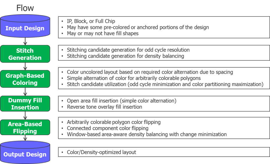
We have found that it is better to bring an array of tool capabilities that can be mixed and matched to provide the best solution in a particular application space. This versatility not only helps designers adapt to different requirements, options, and flows, but it also allows each tool to be optimized for the function(s) that it performs both in quality of results and performance. Figure 4 shows a flow for producing a design that is well-balanced for color, using an array of automated tool capabilities.
Figure 4: Color density balancing flow.
The first two capabilities have been discussed pretty extensively in my previous articles. They are the fundamental elements of decomposing layouts into multiple colors. The focus here is their ability to affect color balancing. Our SmartFill capabilities in the Calibre YieldEnhancer tool are well documented, but they have been enhanced to insert colored fill when needed, as well. The area-based color “flipping” capability is a solution we built specifically for fine-tuning a design for color balancing. Hold that thought.
Setting up a proper flow and use model is critical. For instance, by inserting colored fill after the circuit is colored, the graph-based engine does not have to process the gigabytes of fill data that might significantly slow the performance. If the simple color alternation capability of the circuit and dummy fill tools is not sufficient to meet all the color density balancing requirements, then the new area-based flipping tool can make some fine adjustments. Keeping the graph-based processing separate from the area-based processing lets both processes work much more efficiently.
Now, back to this area-based flipping solution. The basic idea is that it is best to assess the true color density of a layout after everything has been colored, and you can truly look at it from a windowed area-based view, just like traditional density DRC checks do. At this point, you can identify exactly which windows have a problem, and focus your correction efforts there. All of the previous coloring steps will most likely produce good color-balanced results in most windows. Once you know which windows do not meet the requirements, you can then identify the modifications needed to meet those requirements, while changing as little of the initial coloring as possible.
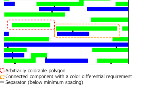
There are two key correction techniques that we bring to this process. We look for polygons that are arbitrarily colored, and for connected components that have a significant delta in color area. Figure 5 shows an example of such design elements.
Figure 5: Portions of layout that can be “flipped” to improve color density balancing.
A separator represents a below-minimum spacing between polygons that requires them to be different colors. Any particular polygon that does not touch a separator is free to be assigned to any color, so you can flip the color of these polygons as needed to improve color density balancing.
Polygons that are connected by separators form a connected component. If a polygon touches a separator, then it must be the opposite color from its connected neighbor. In double patterning, if you flip the color of one polygon in a connected component, then you must flip the colors of all polygons in that component to avoid a coloring conflict. Since all the polygons in a given connected component may not be the same size, the sum of all the area for one color may be significantly different than the sum of the area of the other color.
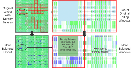
Since windows of density measurement can overlap, and since polygons and connected components can exist across more than one window, using either of these flips can affect the color density ratio of more than one window. Heuristic solver algorithms can be applied to minimize the color density error across all the windows, providing improved balancing results (Figure 6). In this example, the bulk of the layout is made up of arbitrarily colorable polygons and small, connected components with non-uniform color area. There are also very large area polygons that significantly bias the color density, scattered throughout the layout. After original coloring, many windows have color balancing failures due to these large polygons. The area-based flipping process uses heuristics to identify a minimal set of arbitrarily colorable polygons and connected components to flip, fixing most of the issues in the design. However, notice that color flipping is not always able to resolve all density balancing issues in a design.
Figure 6: Flipping a design layout to correct density balancing failures after initial coloring.
Balancing the color density in a multi-patterned design is just another manufacturing constraint that designers must live with at advanced nodes. Expect to see DRC checks for these constraints in your rule decks. Mentor will continue to build and enhance design automation tools to assist you with meeting these new design constraints. Getting educated on what the requirements in your particular foundry are, laying out a design flow and methodology that take these constraints into account, and learning about the new tools and capabilities you can bring to bear on them is the best way to make sure you won’t be falling off that tightrope without a safety net.
In my next blog, I want to take a look at how moving beyond two colors impacts error detection and visualization. Just when you thought you had it all figured out based on your experience with double patterned designs, triple and quadruple patterning promise to send you back to study hall. We’ll investigate how to efficiently debug cycle violations in TP and QP. Don’t panic! We worked our way through DP, and I’m confident we can do it with TP and QP as well.
Author
David Abercrombie is the advanced physical verification methodology program manager at Mentor Graphics.
This article was originally published on www.semimd.com
Comments
Leave a Reply
You must be logged in to post a comment.



Thanks for sharing the information.