A flexible flow for inserting embedded compression logic in RTL
By Ron Press
Inserting test compression logic just got a lot easier.

The standard approach for testing IC logic is the use of scan chains, with embedded compression as the standard approach for applying scan patterns. Embedded compression enables the same test quality as traditional scan test, but with hundreds of times fewer test cycles. However, did you realize that the embedded compression logic is independent of the functional logic design? The compression logic can be defined at the gate level or at the RTL level because it only interfaces with the scan chains. In the past, many people would define a framework of what the scan chains are expected to look like (often referred to as a “skeleton flow”) for RTL compression generation. But today, the RTL generation of embedded compression is flexible enough that designers do not need to know the precise number of scan chains and clocking of scan chains. I’ll give some tips on how to avoid a couple of the common problems designers face when inserting compression logic during RTL design. This new, more flexible, skeleton flow can significantly improve your RTL test insertion experience.
Users of embedded compression (such as Tessent TestKompress) are split among those who create the compression logic at the gate-level design after scan chains are inserted and those who create the compression logic during RTL design. Insertion at the gate level is desired by some because the design is more complete and the chains and clocks are known. Others prefer to insert compression at the RTL level because then it can be synthesized with the rest of the design. The trend is growing towards insertion at the RTL level design.
When adding compression to an RTL design, you would typically design the number of scan chains, clocking and edge of the first and last cell of scan chains, and the rough maximum length of the scan chains. The clocking information ensures that the embedded compression that will be wired to scan chains will have appropriate lockup latches, which prevents race conditions between the compression logic and scan chains and when scan chains are concatenated for bypass mode. However, knowing exactly how many scan chains will exist in the design might not be clear at the start of the RTL design. In addition, knowing the clocks and edges at the start and end of every scan chain could be even more difficult to predict.
Even if the number of scan chains and clocking can be predicted correctly and the synthesized design agrees with the prediction, there are often ECOs that could result in more scan chains. Furthermore, some companies are using test point technology to get even more test pattern reduction, but the exact number of test points is often unknown until the gate-level design exists. This adds even more uncertainty to the number of scan chains that will exist in the final design. Fortunately, there is a newer capability that enables embedded compression logic to be defined without needing to know clocks used for any scan cells or the exact number of scan chains.
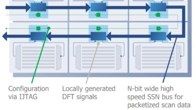
Figure 1. Compression with scan chains that start with leading edge flops and ending in trailing edge flops.
For example, when inserting scan compression logic, there is a risk that the last cell of a scan chain uses a clock that is not synchronous with the first cell of the next scan chain during bypass. To circumvent this issue, the scan chains can simply be defined with a leading edge (rising edge) clock at the first cell and trailing edge clock for the last cell of the chain (Figure 1). As a result, concatenating any chain to another will have half a cycle (trailing edge to leading edge) of timing. So with this configuration the clocking of the scan chains can be arbitrary as long as chains start with leading edge and end with trailing edge.
As for the problem of knowing exactly how many scan chains will exist in the final design, some compression technology is architected so you can over-specify the number of scan chains with no consequences. If some of the scan chains specified end up not being implemented, the compression logic will still work fine. The only requirement in this case is to define the scan chain ports of the compression logic that are not used and to tie the compactor inputs from the unused chains to a logic zero. With these two tips, embedded compression logic can be defined early in the design process with connections for enough scan chains so that ECOs and test points can be accommodated without any changes to the compression logic.
Finally, you sometimes need to define different numbers of tester channels for the same design depending on its usage in multiple SoCs or multiple packages. To accomplish this, take advantage of the flexibility of the compression channels to the tester stimulus, which lets you define the maximum number of channels that might be used. Then, if some channels are not used in a particular package or SoC design, you just tie those channel inputs to zero and the scan compression tool will operate with the used channels. These tips on inserting embedded compression logic in RTL give designers much more flexibility than in past flows. This flexibility can help avoid re-work on scan chains with ECOs and ease the process of test insertion in any SoC.
Author
Ron Press is the technical marketing director of the Silicon Test Solutions products at Siemens EDA.

Liked this article? Then try this –
White Paper: Design Flows Using TestKompress
Press Release: Mentor Graphics New Tessent ScanPro Product Delivers Giant Leap in Test Data Volume Compression
This article was originally published on www.evaluationengineering.com